Continue to Site

Eng-Tips is the largest engineering community on the Internet

Intelligent Work Forums for Engineering Professionals

  • Congratulations waross on being selected by the Eng-Tips community for having the most helpful posts in the forums last week. Way to Go!

How many DOF does datum feature A constrain? 1

Status
Not open for further replies.

SeasonLee

Mechanical
Sep 15, 2008
909
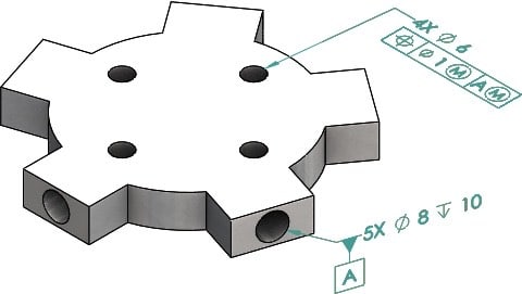
Please ref to the figure below, how many degree of freedom will be constrained by datum feature A (5 holes pattern)? 4, 5 or all 6 DOF?
IMG_8206_ncbqcn.jpg


Thanks

Season
 
Replies continue below

Recommended for you

Thanks. Burunduk

Would you please interpret more in details the reason why all 6 DOF constrained in this case. If so, Will the datum point be the intersection of these 5 axes?

Season
 
SeasonLee,

The datum feature simulator for the pattern of 5 holes which is datum feature A is a structure of 5 fixed-size* pins, the axes of which lie on a plane.
When you engage the pins with the part, except for the ability to rattle it a bit due to datum shift, the part will be immobilized in rotation and translation in all directions.

The datum derived from the above-mentioned datum feature simulator will be 5 axes and a point: the 5 axes of the pins that construct the simulator, and their intersection point in the center of that structure. This point will be the best candidate for the origin of the datum reference frame 'A(M)' and the coordinate system that can be associated with it, for the purpose of controlling the position of the four ø6 holes.

*As a side note, to determine the size of the pins for the simulator, a position tolerance without datum references controlling the spacing and alignment of the 5 holes should have been specified, defining the pattern's permissible variation and allowing to calculate the MMB.
 
If the object is fixed in space and the pin fits snugly into the hole, there are two degrees of freedom: longitudinal translation, and rotation about the pin. Therefore there are four constained DOFs. If the pin 'screws' into the hole and is fixed against rotation, there are no DOFs, or six constrained DOFs.

So strange to see the singularity approaching while the entire planet is rapidly turning into a hellscape. -John Coates

-Dik
 
dik,
Notice that datum feature A is the pattern of 5 holes ("5X") and not a single hole.
 
Sorry... misunderstood the problem; I thought it was only related to datum feature A.

So strange to see the singularity approaching while the entire planet is rapidly turning into a hellscape. -John Coates

-Dik
 
Hi All,

I agree with Burunduk's explanation - this is almost exactly what I would have said.

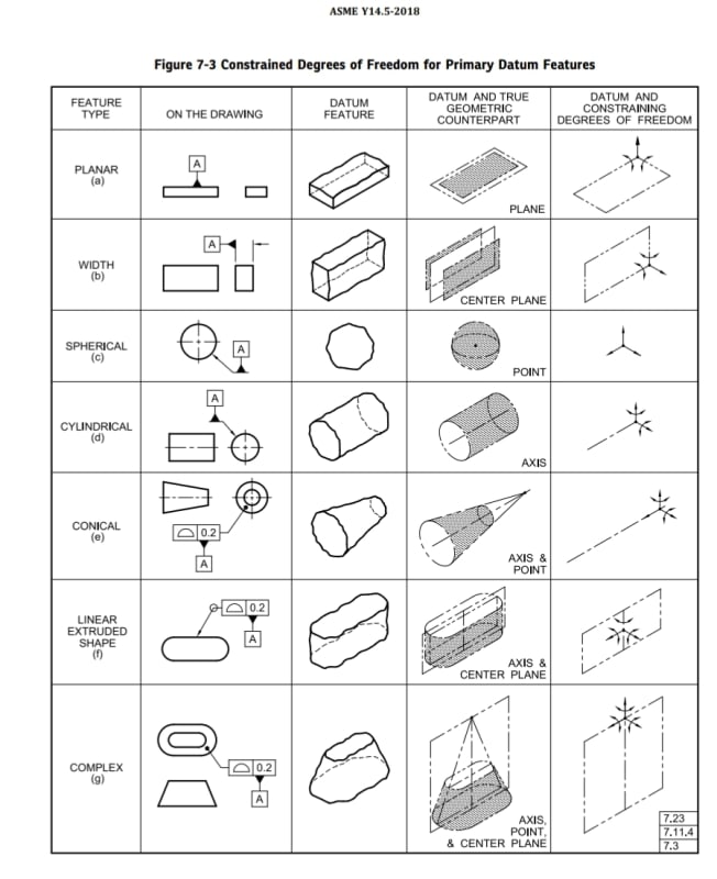
In general, Y14.5's theory and definitions for TGC's / datum feature simulators are clear and we can assess the degree of freedom constraint from those. The theory for datums is much more limited and problematic, especially for multiple datum features (now called "common" datum features in 2018). If you look at the table in Fig. 4-3 of Y14.5-2009 or Fig. 7-3 in 2018, the 5-hole pattern is a "complex" datum feature (row g in the table) and the datum would be an axis, point, and center plane.

I would say that for even moderately complicated datum features such as hole patterns, the concept of datums isn't much use at all. The TGC's are always well defined, but the datums can be quite arbitrary.

Evan Janeshewski

Axymetrix Quality Engineering Inc.
 
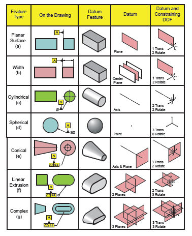
Evan, the datums are certainly less rigorously defined and I see it, too, that they often quite arbitrary, and it is so to the point that committee members who also own training companies seem to offer their own versions of Fig. 4-3 of Y14.5-2009 or Fig. 7-3 in 2018. See below the version from GeoTol versus the figure from the standard.

I actually like the datums shown in rows (e) to (g) better in the GeoTol version, because they are more direct in the process of establishment of 3 planes DRF, and this is what I think the purpose of datums is anyway. However, I never quite understood - why is a primary datum axis, such as the one derived from a cylinder or a cone, doesn't automatically come along with the two datum planes intersecting on it at right angles? This could be shown in these figures because that is what is done at DRF establishment anyway isn't it?

I don't necessarily associate the pattern of holes in the OP's case with row (g). See how the datum point is the intersection of line elements taken from the tapered TGC. There is no direct equivalent to that in the OP's case. There is also no unique center plane, such as the one established along the longitudinal direction of the feature in row (g) and shown in the standard's figure.
I still think that 5 holes provide 5 datum axes, and the point is the intersection of these axes. Then the 3 DRF planes are established on the basis of these axes and the point.

The standard's version:
Screenshot_20221004-085150_Drive_e6dedx.jpg


The GeoTol version:
DOF_qb2xgg.jpg
 
Imagine using a spiral of holes along a part, not sharing any common plane, nor common intersection point, yet they still constrain the part just the same, happening to have multiple nominal intersection points along an axis.

It would be nice to have the process defined by a compact set of rules instead of a series of special case treatments.

In any case none of those are good examples for this case as all of them are from a set of contiguous, mutually tangent surfaces, the sole exception being the width between parallel planes - an interesting exception.

A better label is "INCOMPLETE SUBSET OF POSSIBLE PRIMARY DATUM FEATURES"

Then there is this:

3.66 TRUE GEOMETRIC COUNTERPART
true geometric counterpart: the theoretically perfect boundary used to establish a datum from a specified datum feature.
NOTE: This term is only applicable to datums
vs
7.5 TRUE GEOMETRIC COUNTERPART
A true geometric counterpart, as defined in subsection 3.66, shall be the inverse shape of the datum feature, UOS.

Pick just one complete definition and define it in just one place, please.

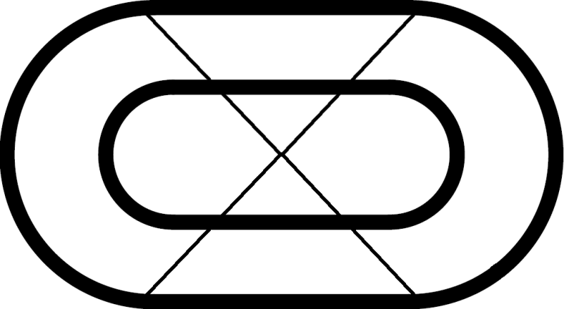
A nitpick on figure G - which is incorrect in "ON THE DRAWING." The tangents on the upper surface and bottom surface should be the same distance apart - that is the flat faces aren't trapezoidal as the diagram shows, they are tilted rectangles. Just bugs me as anyone who has done drafting should spot that a mile away.

The other choice for figure G "ON THE DRAWING" is that they aren't right-cones on the ends, in which case the gap between the inner and outer profiles won't be uniform as depicted - the side slope won't be constant around the part and will be larger at a larger distance.

Either way, the figure is borked.
 
Here is the current Figure G top view extension lines from the bottom edge tangent points to the vertex:

G_aq8j8s.png


Those lines should go through the matching tangent points on the top edge - clearly they do not.

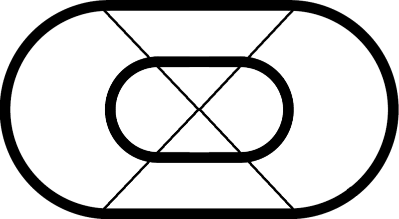
This is correct for a single vertex solution:

G_correct_zheoc4.png
 
Status
Not open for further replies.

Part and Inventory Search

Sponsor