Continue to Site

Eng-Tips is the largest engineering community on the Internet

Intelligent Work Forums for Engineering Professionals

  • Congratulations pierreick on being selected by the Eng-Tips community for having the most helpful posts in the forums last week. Way to Go!

How quadrilateral elements represented in most FEA solvers for structural mechanics problems?

Status
Not open for further replies.

Eugene Pavlov

Mechanical
Nov 10, 2020
4
How quadrilateral elements represented in most FEA solvers for structural mechanics problems?

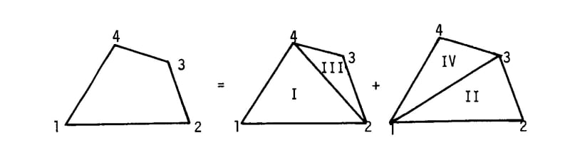
I know that Nastran-95 represent quadrilaterals for membrane and bending elements as a set of triangles:
q_to_tria_l2btga.jpg


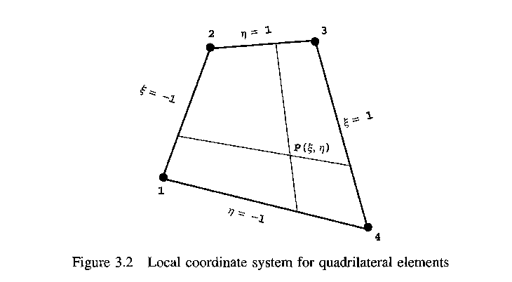
At the same time there are a lot of literature where stiffness matrix for quadrilaterals is computed using ξ-η coordinates:
q_ksi_eta_jktw8m.png


The question is which one of both methods is used in modern FEA packages?
 
Replies continue below

Recommended for you

I assume that you are talking about quadrilateral shell elements. From what I know, in most FEA packages (like Ansys or Abaqus) the latter approach is used as it’s the standard one.
 
Dear Eugene,

FORMULATION FOR PLATE & SHELL ELEMENTS with Simcenter NASTRAN

The general idea in the Element Formulations of the Finite Element Method (FEM/FEA) is that shear force deformations are included in the calculation according to Mindlin, but are neglected according to Kirchhoff. This means the following: For thicker plates and shells, the Mindlin theory leads to good results, for thin plates, the Kirchhoff theory.

In Simcenter Nastran the formulation of the CQUAD4 elements are based on the Mindlin-Reissner shell theory. These elements do not provide direct elastic stiffness for the rotational degrees-of-freedom which are normal to the surface of the element. Instead, CQUADR are improved isoparametric plate elements that takes advantage of the normal rotational degrees of freedom (which have no stiffness associated with them in the standard plate elements) to provide improved membrane accuracy. The software computes a rotational stiffness about the normal to the element at the vertices, which is used in the formulation of the element stiffness. Consequently, this degree-of-freedom must not be constrained unless it occurs at a prescribed boundary. The CQUADR element provides better performance for modeling planar structures with in-plane loads than CQUAD4.

The Simcenter Nastran PSHELL entry defines the membrane, bending, transverse shear, and coupling properties of thin plate and shell elements. We use the PSHELL entry to define the material ID for the membrane properties, the bending properties, the transverse shear properties, the bending-membrane coupling properties, and the bending and transverse shear parameters. By choosing the appropriate materials and parameters, virtually any plate configuration may be obtained.

pshell-format_ef0jky.png


The CQUAD4 element can model in-plane, bending, and transverse shear behavior. The element’s behavior is controlled by the presence or absence of a material ID number (MID) in the appropriate field(s) on the PSHELL entry.

• Use MID1 if you want to include membranes only (no bending).
• Use MID2 (and optionally, MID3) if you want to include bending only.
• Use MID3 to have the Simcenter Nastran software use thick plate theory, which includes the transverse shear flexibility, to develop the element stiffness matrix. In general, for thin or curved surfaces, you should not use MID3.
• Use MID4 to input a coupling relationship between the in-plane forces and bending moments. This coupling only occurs in plates that are non-symmetric about the neutral plane or where the neutral plane is offset from the grid points. Typical applications include reinforced skins and aluminum bonded to fiberglass. You should leave the MID4 field blank if the element cross section is symmetric.
For a solid, homogeneous, thin, stiff plate, use MID1, MID2, and MID3 (all three MIDs reference the same material ID).

Adding transverse shear flexibility means that using MID3 adds a shear term in the element’s stiffness formulation. Therefore, a plate element with an MID3 entry will deflect more (if transverse shear is present) than an element without an MID3 entry. For very thin plates, this shear term adds very little to the deflection result. For thicker plates, the contribution of transverse shear to deflection becomes more pronounced, just as it does with short, deep beams.
The following image is from FEMAP to define the plate properties for 2-D Shell CQUAD4 elements:

pshell-prop_zl0i1y.png


ELEMENT FORMULATION FOR NONLINEAR ANALYSIS

With Simcenter Nastran the important KEY is the following: the formulation of a shell element is dependent of the solution type where the SHELL element is used,.

For instance, the CQUAD8 and CTRIA6 element formulations that the Simcenter Nastran software uses with the Nonlinear Multistep Analysis (SOL401/SOL402) module are different from the CQUAD8 and CTRIA6 element formulations that the software uses in the other solution sequences like Linear Static (SOL101) or Nastran Basic NonLinear (SOL106).

The SOL401/402 formulations for SHELL elements have several advantages over the formulations used in the other solution sequences, for instance:

• They allow for higher aspect ratio of length to thickness before shear locking occurs.
The CQUAD8 formulation is a heterosis formulation: The CQUAD8 heterosis formulation uses eight-noded serendipity shape functions for the translational DOF, and nine-noded Lagrange shape functions for the rotational DOF. The enriched shape functions lead to better results although at some computational cost.
Because a ninth grid point is required for Lagrange shape functions and only eight actual grid points exist, the software creates internal DOF at the centroid of the element. The internal DOF functions as the ninth grid point for the element. After calculating the element matrices, the software condenses the internal DOF prior to assembly into the global matrices.
By default, four Gauss points (2 x 2 integration) are used to integrate the membrane and transverse shear stiffness, and nine Gauss points (3 x 3 integration) are used to integrate the bending and coupled membrane-bending stiffness.
• The formulations use the K6ROT parameter to suppress grid point singularities by adding stiffness to the out-of-plane rotational DOF.
• When viewed normal to the reference plane of the element, the X- and Y-axes of the material coordinate system are consistent across the element. In the element formulations that are used in other solution sequences, the X- and Y-axes of the material coordinate system vary across the element.

For nonlinear analysis, Geometric Nonlinear effects should be significant if the deformed shape of the structure appears distinctive from the original geometry by a visual inspection. A more rigorous and quantitative definition for the large displacements can be derived from the plate theory of Kirchhoff-Love: the small deflection theory is valid for a maximum deflection of less than 20% of the plate thickness or 2% of the small span length. The method I follow is the following: if the resultant displacement is in the order of the Shell element thickness, then the problem should be solved as nonlinear.

Well, I hope the above information helps you to understand the "rich" capabilities of the Simcenter Nastran solver integrated with FEMAP.
Best regards,
Blas.

~~~~~~~~~~~~~~~~~~~~~~
Blas Molero Hidalgo
Ingeniero Industrial
Director

IBERISA
48004 BILBAO (SPAIN)
WEB: Blog de FEMAP & NX Nastran:
 
Status
Not open for further replies.

Part and Inventory Search

Sponsor