Hello together,
I have a question about the interactions and constraints in Abaqus.
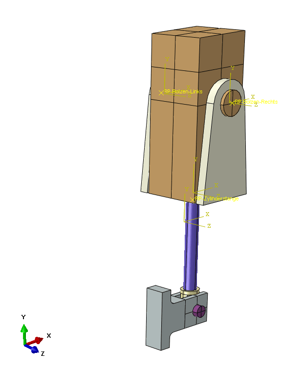
I am doing a static analysis and I am modeling a cylinder that is rotatable on two sides (see picture). The cylinder rod is movable in y-direction and pushes with a force on a plate via a lever. I am now wondering what constraints and interactions I need to use for the rotating support and the moving cylinder rod. Currently I have Contact defined for the cylinder rod and the hole of the cylinder. However, an eigenvalue problem arises during the simulation. Then I defined a reference point in the center of the cylinder rod and used Coupling to relate the area of the rod to this point. With the help of a displacement constraint I restricted the movement, but the result does not correspond to reality. I have the same problem with the rotatable bearing. I have defined a Contact and then used an RP and Coupling to constrain the movement. However, the cylinder does not rotate in the result although it should through the lever. Do any of you have ideas? In itself, I understand how the system works, but I do not know how to get it translated into Abaqus.
I would be very grateful for any tips and suggestions.
Many greetings!
I have a question about the interactions and constraints in Abaqus.
I am doing a static analysis and I am modeling a cylinder that is rotatable on two sides (see picture). The cylinder rod is movable in y-direction and pushes with a force on a plate via a lever. I am now wondering what constraints and interactions I need to use for the rotating support and the moving cylinder rod. Currently I have Contact defined for the cylinder rod and the hole of the cylinder. However, an eigenvalue problem arises during the simulation. Then I defined a reference point in the center of the cylinder rod and used Coupling to relate the area of the rod to this point. With the help of a displacement constraint I restricted the movement, but the result does not correspond to reality. I have the same problem with the rotatable bearing. I have defined a Contact and then used an RP and Coupling to constrain the movement. However, the cylinder does not rotate in the result although it should through the lever. Do any of you have ideas? In itself, I understand how the system works, but I do not know how to get it translated into Abaqus.
I would be very grateful for any tips and suggestions.
Many greetings!