Continue to Site

Eng-Tips is the largest engineering community on the Internet

Intelligent Work Forums for Engineering Professionals

  • Congratulations waross on being selected by the Eng-Tips community for having the most helpful posts in the forums last week. Way to Go!

How to analyze plate assembly at the top of this structure?

Status
Not open for further replies.

MJC6125

Structural
Apr 9, 2017
119
I have to analyze the steel structure in the picture below.
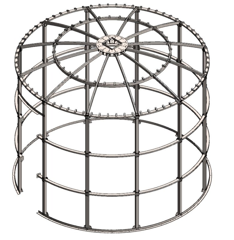
Capture_1_g0vme9.jpg


I'm having trouble figuring out how to analyze the center hub at the top of the dome. In the next picture below you can see that there is a slight rise to the structure in elevation view.
Capture_2_juu91d.jpg


The final picture is an enlarged view of the center hub. As you can see it has a hole in the middle of it. So far, I tried analyzing it as a single layer of steel plates in Risa with a hole in the center, but I'm getting a P-Delta diverging issue. Anybody have any ideas on how to analyze this? Do you think it will work as shown? Any insight would be helpful.
Capture_3_xgqdhc.jpg
 
Replies continue below

Recommended for you

You say you are modeling it as a "single layer of steel plates". But looking at it.....that doesn't appear to be what it is. You may want to model it as closely (or as practically) as possible and see what happens.
 
Because of the shallow 'snap through', you may have difficulty modelling the 'ring beam' in torsion. Can you move the opening between the 'ribs'?

Dik
 
some concepts are just not structurally feasible.....I would first push for a solid ring...right now, I do not see any structural element there that could be analyzed with any degree of confidence...
 
Besides your primary question - how does this gizmo work when you have unbalanced loads on one side of the dome?
Seems that this plate assembly would rotate about a horizontal axis and depend on those four-bolt connections at the ends of the ribs to be moment connections.

Check out Eng-Tips Forum's Policies here:
faq731-376
 
The ribs would have much more moment capacity if they were extended to the inside of the hub, so that they would be 'sandwiched' between the top and bottom plates. Even better if you put a solid ring (except for a bolt hole for each rib) around as far toward the center of the hub as possible and attach the ribs to it. Then add web plates or stiffeners around the outside perimeter of the hub between the ribs (a ring around the outside with openings for the ribs to pass through. You'd have to dispense with the outside end plate on the ribs and go with a tapped and threaded cap or plug on the end of the ribs to secure them at the inside ring.
 
I've had a similar arrangement, but made the connections to the hub moment connections. Take a cross-section through the hub, sum moments about that line, and you can find the moment in the hub itself in that case.
Roark includes a case for a circular ring with N radial loads.
You'd either be depending on a moment connection to the beams or a torsional connection at right angles to the beam in question to prevent the whole hub from flopping sideways.
 
Status
Not open for further replies.

Part and Inventory Search

Sponsor