Continue to Site

Eng-Tips is the largest engineering community on the Internet

Intelligent Work Forums for Engineering Professionals

  • Congratulations IDS on being selected by the Eng-Tips community for having the most helpful posts in the forums last week. Way to Go!

How to apply remote mass in Abaqus?

Status
Not open for further replies.

W1nther

Civil/Environmental
Nov 28, 2019
9
Hi

I'm trying to model some additional mass at some distance from a cantilever beam. But I can't figure out how I would do that so some advice would be very nice.
I have tried drawing my problem, please see the attached image.
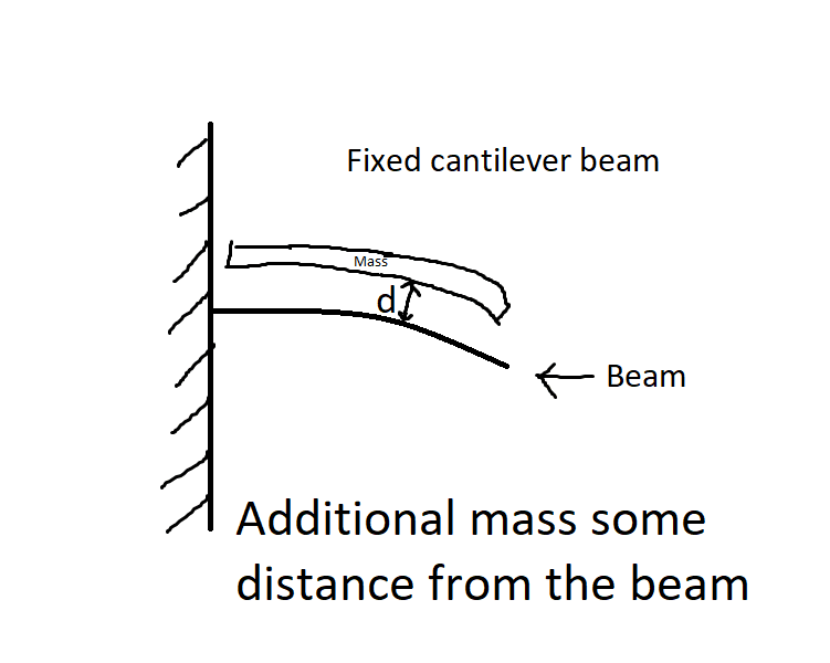
helpplease_zxe9yq.png


What I've tried:
I have tried creating an extra beam with nonstructural mass above my cantilever beam only connected with beam connectors but I can't connect to each node only some points in each end of the beam. This obviously won't give the correct eigenfrequencies.
 
Replies continue below

Recommended for you

The way to model this depends on how it would look like in real life. You can use point mass feature and connect this point to the beam via coupling or connector.
 
I'm wondering how this structure looks like in reality and how those two regions are connected.

Try this:
Model truss elements with low stiffness at the mass location. Apply the nonstructural mass to those elements. Tie them to the beam. Increase the position tolerance to overcome the gap and do not activate adjust.

Run a datacheck and check if it really worked with the tie constraint.
 
Yes I know how to add mass to the points, sorry I should have been more clear. I want a distributed mass on the beam but with a distance, so essentially I want to know how I can make connectors between every mesh-node on my beam to the nodes on my 'mass beam'. Well unless there is a smarter way to simulate it.
 
Coupling constraint should handle this. You can connect the reference point with assigned mass to the whole beam.
 
Hi Mustaine
This is just a school problem, so it doesn't exist in real life. I'm trying to model a 2D frame with some live load and perform a frequency analysis to obtain the modes. Problem is that it would be wrong to just increase the density of the beam itself because the center of mass for the live load is some distance above the beam. Also i want the mass to follow the beam deflection when I put a load on it.
 
Thank you FEA way
I will try to get your suggestion to work.
 
I did some tests in Abaqus today and unfortunately the method with single offset point mass coupled to the whole beam won’t work. However I’ve found another way. Create offset point mass above each node of the beam (so that there are as many point masses as beam mesh nodes) and assign proper portion of the total mass to each of these points (for example if there are 20 nodes/point masses and your total offset mass is 10 kg then apply 0,5 kg to each point). Then connect each point mass to corresponding node of the beam using BEAM type MPC. Make sure that you select point mass as first point and beam node as second one:

*MPC
BEAM, point_mass_1, beam_node_1

You will have to create multiple nsets and elsets as well as separate point mass and MPC definitions but this can be done relatively quickly if you use both CAE and input file to set this up.
 
Hi FEA way
Thank you very much for your help.

Your solution worked for me. It is a bit unfortunate that I have to make multiple sets since this limits scaling the solution to a large 3D model. It would be too tedious to create all those constraints for a model with many nodes. Maybe I could create a script for it eventually. I think i will try to investigate how much influence moving the mass has for my model with your solution and then compare it to the response I get when I just increase the density of my beam. If its negligible then it will be easier for me to just increase the density and accept that small error i will have.

Once again, thank you for taking your time to help me, it is much appreciated.
 
This method requires some effort but it can be automatized. Using scripts, as you say but some tricks in CAE and input file can also make it relatively fast. For example you may easily create offset points above the beam (one way to do this is to create offset shell layer above the 3D beam, define nset with its nodes, assign point masses to this nset and the delete elements belonging to this layer). The rest generally consists of repetitive definitions (of sets, point masses and MPCs). It will be fastest to create them directly in the input file (using some tricks that can be applied depending on the text file editor) or via scripting.

There is a plug-in called Create Engineering Features that can be very helpful in this case because it allows you to automatically create beam type MPCs between each node of the surface of the beam and corresponding offset node. To find this plug-in search Dassault Systemes Knowledge Base for "Abaqus/CAE plug-in application to automatically generate point-to-point springs, dashpots, MPC constraints, or wires for connectors".
 
Status
Not open for further replies.

Part and Inventory Search

Sponsor