Eng-Tips is the largest engineering community on the Internet

Intelligent Work Forums for Engineering Professionals

  • Congratulations waross on being selected by the Eng-Tips community for having the most helpful posts in the forums last week. Way to Go!

How To Build Assemblies from Excel

Status
Not open for further replies.

jzecha

Aerospace
Jan 20, 2016
235
US
Does anyone have any good demos or reference material on how to build simple standard assemblies from an Excel sheet?

I realize this will require some sort of Macro, but I have searched a lot and have not come up with much to help me learn how to do this.
I only find people who have done this and them showing it off.

What I am after is building a scaffolding deck assembly which only consists of 10 different parts, but duplicates of most of these parts.
One of our customers provides us with a Standards Callout in the BOM and i want to be able to put in the called out "length/Width of the deck and it builds the deck for me.

I just do not know how to create and place parts from excel into Catia.
 
Replies continue below

Recommended for you

You'll need .CATPart path and positioning matrix (location and rotation). Do you have them in the Excel workbook?
 
Little Cthulhu,

I have a very basic setup to get what I needed done.
I setup a bunch of Inputs and then had Excel calculate a bunch of information I pushed into parameters that drove my model sizes and instances.

This worked, but does not create new instances of details or delete unneeded instances if my decking is smaller or larger than the initial size.

I made this post for hopes someone could share a simple setup they have that I can mimic or somewhere where it shows me how to set all of this up.

LWolf,

Your link is kind of what I am after, my searching was ruined by added "Excel" because I cant find anything except importing points.
I will use this as a possible way to get this accomplished, but if you have any more info, that would be greatly appreciated.

I really need to specify a few inputs and let Excel calculate some info and then let it build the parts, that are different based on the input dimensions.
 
so your p;rocess is like a 3 steps process:

1: input parameter in excel
2: do excel magic to define assembly in excel
3: build catia assembly based on excel assembly

are part 1 and 2 done and your question is about 3 only ?

Eric N.
indocti discant et ament meminisse periti
 
Pretty much I need to figure out how to accomplish number 3.

But I am sure once I figure out how to do number 3, I will need to create more info in Excel to assist in the building of the Parts and Locating them in the Assembly.
 
If I'm understanding the original problem, you have the same 10 components in one assembly? I'm assuming the components are constrained in a standardized arrangement.
I've tackled something similar without the use of scripting. It's by no means a 100% successful solution, but it saves me a lot of time on 95% of the projects I use it for. I had absolutely no idea how to write code when I made this template assembly so that's not really a factor. Now that I am able to fumble my way through some coding, it most defiantly could have a nice VBA/userform incorporated into it.

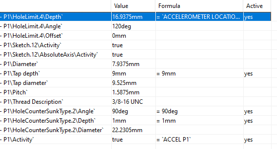
When you use the Formula toolbar/menu just pick the item on the screen and it wil sort to all the aspects about that feature you can control/create relations/formulas with.
Example with just 1 hole feature:
Hole_j817lv.png


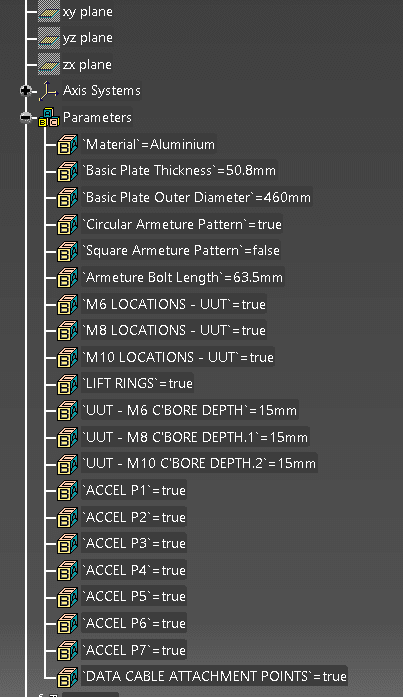
I start with a basic assembly with all my components and use parameters to manipulate sizing. The parameters I show at the bottom control the entire assembly with about 9 unique catparts.
ex:
[ul]
[li]I have a circular plate with bolt patterns, threaded inserts, bolts, washers, etc.[/li]
[li]I use parameters to enter sizing of the plate/dimensions/constraint offset values/hole c'bore/thread/create complex formulas and relations[/li]
[li]I alter the sketch for each bolt pattern. alot of the dimensions are driven by relations/paramters. If I need to leave a bolt location un-used, I just make the point into a construction element.[/li]
[li]Additional boolean parameters activate/deactivate additional bolt patterns/components/constraints[/li]
[/ul]
Once I make all the parameter/sketch adjustments, I just hit update and it populates all the material sizes/component quantities/positions

Features typically used in the assembly:
[ul]
[li]User patterns - part design workbench[/li]
[li]Re-use pattern, this uses your patterns to populate component quantities. Even more powerful in V5R25 and above. You can use axis systems within your user patterns to control 3D orientation - assembly design workbench[/li]
[li]Hole command with all inputs linked to parameters/formulas[/li]
[li]Flexible/Rigid assemblies/cat components(assembly workbench)[/li]
[/ul]
Params_epjqag.png


Another idea would be to link all your components to a skeleton. this is a seperate catpart with a construction geometry matrix you constrain the rest of the parts to.

**Edit** I haven't had the time to try but I've been meaning to create a template drawing linked to the above assembly. It would be useful to have some of the parameters linked into the drawing
 
Status
Not open for further replies.

Part and Inventory Search

Sponsor

Back
Top