hirschaplin
Petroleum
Hello,
When designing PD blower packages there is always a returning document deliverable that disturb me a little bit:
"Civil and Foundation Drawing with total weight, anchor bolt location dynamic forces and moments"
The disturbing part is the dynamic forces and moments as it seems like none of the big PD blower manufacturers provide clear guidance on how such loads shall be calculated.
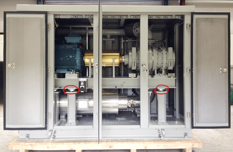
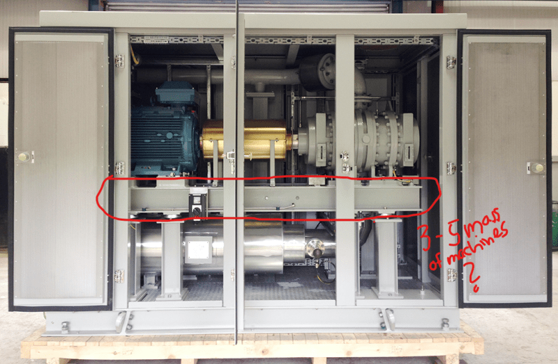
Then I came across a foundation drawing that was made by Howden Roots for a single package with two blowers driven by a common electric motor - and to my surprise they provided a table with static and dynamic loads!
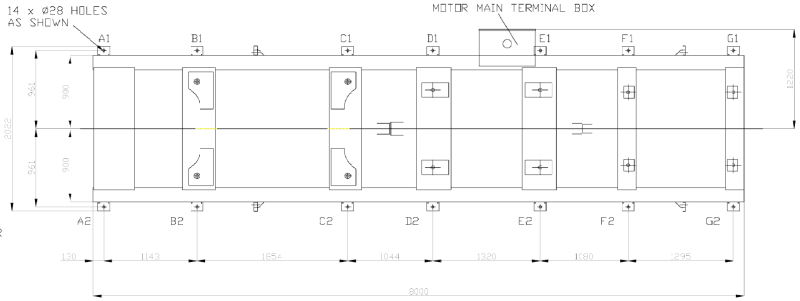
Overview of the skid with load points indicated:
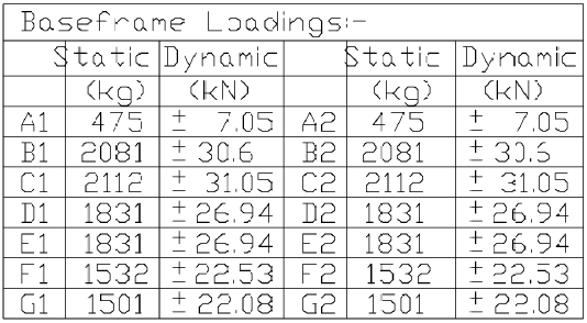
Load table:
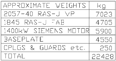
Weight table:
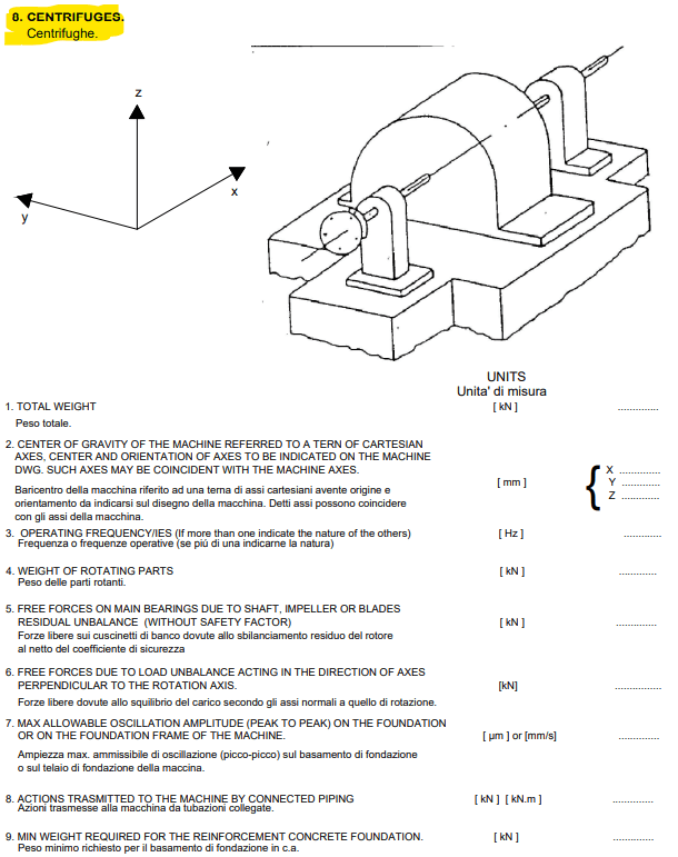
Then I was recently involved in a project with a big European contractor and they have a specification for what input data they require to be supplied in order for them to design a foundation themselves for rotating machines, with the following scope text: "THIS STANDARD RESUME THE FLOW OF INPUT DATA NEEDED TO CORRECTLY DESIGN THE FOUNDATION OF ROTATING MACHINERIES".
Very interesting, I was expecting to finally get some clarity on how to handle the issue with dynamic loads - a general approach that I can apply in all my projects if you want. But no, the darn specification only show which data they require, not how to use it:
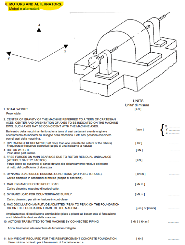
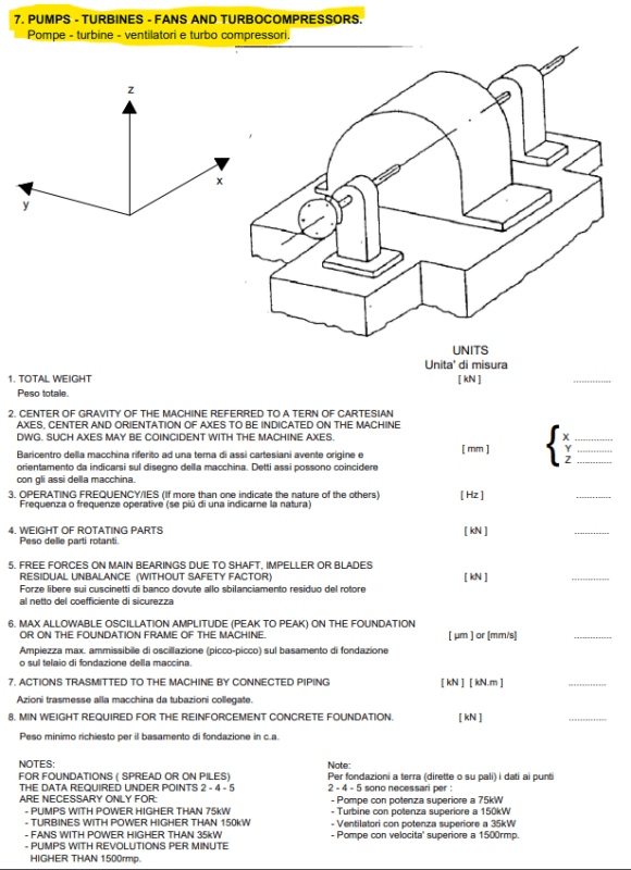
No clear category match for PD blowers, but I would assume it would fit best under "7. PUMPS - TURBINES - FANS AND TURBOCOMPRESSORS.", do you agree? I guess with all this input data, they have enough to calculate all loads by themselves. How are they doing that, how can I use this input data to establish relevant dynamics loads for any PD blower I might use in my projects?
In my packages, the blower is most often direct driven but occasionally we use v-belts. Will the dynamic loads be different for the same machine and operating data but with different driving method?
I am not super concerned by my lacking skills... Today we design our foundations without calculating dynamic loads, just going big and bulky. It is working but I don't like to just follow my guts feeling, I want a decision to be driven by facts or engineering data because I guess it is just a matter of time when something actually goes really wrong with this current approach. But I am also not sure how big of a problem it really is as it seems like dynamic loads are pretty low for PD blowers.
I recently did a FAT of a 250 kW blower. The skid was standing on top of 6 small 5 mm dia. spot supports, 35 cm above floor level, without being locked in place with bolts or something similar. The skid didn't move a millimeter at full load and vibration levels at around 3-4 mm/s RMS on blower casing above bearings. No vibrations in the skid structure.
Loads on the Howden Roots drawing are quite big numbers, but it seems like maybe the loads are taking out each other as they are same on both sides and therefore not very impactful to the design of a concrete foundation? Please elaborate...
But how to approach it? It is awkward to NOT provide dynamic loads or have a good way to talk about it.
When designing PD blower packages there is always a returning document deliverable that disturb me a little bit:
"Civil and Foundation Drawing with total weight, anchor bolt location dynamic forces and moments"
The disturbing part is the dynamic forces and moments as it seems like none of the big PD blower manufacturers provide clear guidance on how such loads shall be calculated.
Then I came across a foundation drawing that was made by Howden Roots for a single package with two blowers driven by a common electric motor - and to my surprise they provided a table with static and dynamic loads!
Overview of the skid with load points indicated:
Load table:
Weight table:
Then I was recently involved in a project with a big European contractor and they have a specification for what input data they require to be supplied in order for them to design a foundation themselves for rotating machines, with the following scope text: "THIS STANDARD RESUME THE FLOW OF INPUT DATA NEEDED TO CORRECTLY DESIGN THE FOUNDATION OF ROTATING MACHINERIES".
Very interesting, I was expecting to finally get some clarity on how to handle the issue with dynamic loads - a general approach that I can apply in all my projects if you want. But no, the darn specification only show which data they require, not how to use it:
No clear category match for PD blowers, but I would assume it would fit best under "7. PUMPS - TURBINES - FANS AND TURBOCOMPRESSORS.", do you agree? I guess with all this input data, they have enough to calculate all loads by themselves. How are they doing that, how can I use this input data to establish relevant dynamics loads for any PD blower I might use in my projects?
In my packages, the blower is most often direct driven but occasionally we use v-belts. Will the dynamic loads be different for the same machine and operating data but with different driving method?
I am not super concerned by my lacking skills... Today we design our foundations without calculating dynamic loads, just going big and bulky. It is working but I don't like to just follow my guts feeling, I want a decision to be driven by facts or engineering data because I guess it is just a matter of time when something actually goes really wrong with this current approach. But I am also not sure how big of a problem it really is as it seems like dynamic loads are pretty low for PD blowers.
I recently did a FAT of a 250 kW blower. The skid was standing on top of 6 small 5 mm dia. spot supports, 35 cm above floor level, without being locked in place with bolts or something similar. The skid didn't move a millimeter at full load and vibration levels at around 3-4 mm/s RMS on blower casing above bearings. No vibrations in the skid structure.
Loads on the Howden Roots drawing are quite big numbers, but it seems like maybe the loads are taking out each other as they are same on both sides and therefore not very impactful to the design of a concrete foundation? Please elaborate...
But how to approach it? It is awkward to NOT provide dynamic loads or have a good way to talk about it.