Eng-Tips is the largest engineering community on the Internet

Intelligent Work Forums for Engineering Professionals

How to calculate soil load on underground bridging slabs? 1

Status
Not open for further replies.

atef81

Structural
Jan 7, 2010
12
0
0
AU
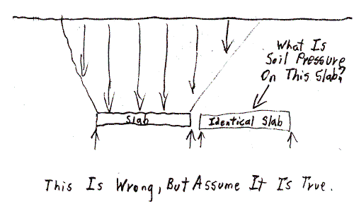
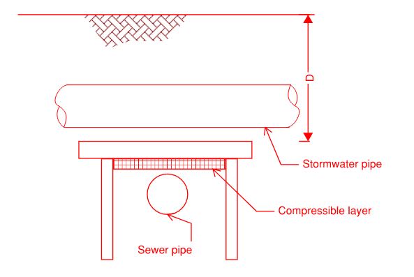
I am required to design bridging slabs above a sewer line, as per the sketch below. The criteria is not to transfer loads to the sewer line, hence the need for a slab. the slab will be supported on 4 piers, so it is a suspended slab.
My question is: how much soil weight does this slab carry? is is simply soil density x depth "D"? or does the soil weight disperse somehow?
So if the distance "D" was 100m (hypothetically) in a 19kN/m^3 soil, does the dead load (soil weight) becomes 1900 kPa?
Thanks in advance.
zx_mggmkv.jpg
 
Replies continue below

Recommended for you

An interesting problem. Your theory is correct in that overburden stress is unit weight times depth (but also consider the effect of groundwater).

The question is, what width do you take it acting over. I think there will be some soil arching effect. So soil that is not directly over the slab will also be adding load to the bridging slab.

I haven't had a a chance to google the problem and see if there is any literature. If it were me I would model it in a 2D FEM program like Plaxis.

Then check if there is any literature out there that can be consulted to verify your results.

 
atef81 said:
So if the distance "D" was 100m (hypothetically) in a 19kN/m^3 soil, does the dead load (soil weight) becomes 1900 kPa?

Yes, the soil is horizontally in equilibrium with surrounding soil... but you need to account for the weight of the stormwater pipe directly above the bridging slab minus the weight of the soil the stormwater pipe displaces. Also, assume the stormwater pipe directly above the bridging slab is full and add the weight of that water.

There probably should be an assumed surcharge load at the surface to account for "anything" (people, vehicles, equipment, storage, etc.) that may pass over or be placed on the surface directly above the bridging slab.

As ErieChch mentioned, groundwater could be another consideration.

[idea]
 
Thanks @EireChch and @SlideRuleEra. I am assuming that there is no ground water at the moment. Also, I accounted for wheel loads to Australian Standards AS5100.2. I am also considering the stormwater pipe to be full. But my question in more related to the soil weight above the slabs. One of my colleagues believe that weight of the soil gets dispersed out after a certain height above the slab. I can't find any literature to support this.
 
@ErieChch, can you please elaborate on the soil arching effect you mentioned? is it possible to sketch it so I can understand? thanks in advance.
 
atef81 said:
One of my colleagues believe that weight of the soil gets dispersed out after a certain height above the slab. I can't find any literature to support this.

Your colleague's opinion is understandable, but not true. That is why you can't find support. Your colleague would be right, if, you were trying to lift the underground slab... but you are not trying to lift it... it is static. Consider this sketch, ask you colleague what would be the soil load on the identical nearby slab, both of them static. The answer has to be the load is the the same on both slabs. But if your colleague's assumption was true, load on the identical slab will be lower... which goes against the laws of physics. This is tricky, but think about it.

Buried_Slab-500_l5bs16.png


[idea]
 
IMO, the soil at each end of the slab will help support the soil over the slab by arching. It seems to me that the sloping above each slab support point should be sloping toward the surface, above the center of the slab. Therefore, the sloping would reduce the load on the slab, just like is assumed due to arching in the design of lagging boards.

 
If the supported slab were to push upward, then the slopes of the soil loading would angle up and away from the slab edges. But the soil is loading the slab downward so some of the load might be reduced due to arching in competent soil. The wider the slab, the less significant the arching and reduction are. I probably would ignore any load reduction on the slab and just use a rectangular soil load (plus any surcharges). I don't see how there could be a water surcharge on top of the slab and a water-filled pipe will most likely weigh less than the soil it displaces. I would probably ignore the weight of the water-filled pipe and assume full soil above the slab.

 
I still believe that the slab will take more load than just the vertical column above it. Because the slab is fixed, the soil either side wants to move by it, but as there is a frictional/cohesive component "connecting" it to the soil element within the vertical column. This adds more load to the vertical column.

With arching between two piles, similarly, more load is transferred to the pile, than the load from the soil sitting directly behind its width/diameter. Soil supports itself due to arching, but this arching adds more load to the piles on either side of the opening.

Capture_lluxyo.jpg


I found the below paper, which discusses loads on buried pipes. I think your slab is similar to a rigid pipe.


Screen shot from introduction below.

Capture_igfbv9.jpg
 
I agree with EireChCh. Imagine sticking a pencil through a sponge and then putting a load on top of the sponge. The pencil will pick up more of the load because it is more rigid than the surrounding sponge.
 
By your thinking, it seems to me that a lintel in a brick wall should support more load than the rectangular amount of brick directly above the lintel. However, the lintel is designed for a triangular amount of brick weight over the lintel. We probably could have to debate the stiffness of the wall vs. the stiffness of the lintel that sits on the wall.

 
"Because the slab is fixed, the soil either side wants to move by it, "
Why? Its been there for a long long time. Now it wants to move?

It is the newly disturbed soil above the pipe that is moving (compressing) that is developing an arching effect.

Go with the arching philosophy, realising that load on the pipe will probably be more than than the conservative load of an equivalent hydrostatic weight of everything above the slab, as the soil to each side of the pipe compresses. That results in a triangular load from above, point downward. It is the reverse of a lintel load, point up, because the bricks on the sides of the lintel do not compress as the soil does. Due to friction of the compressing newly disturbed soil near the trench walls, which will resist soil compression in that region, the width of the triangular load need not be more than the width of the trench.

The COE Engineering Manual
discusses bridging action of soil over a pipe installed in a trench as a function of trench depth to width ratio and pipe diameter.

Practically speaking I have found all of that bridging and arching action is nice to think about, and I use those soil loads for the pipe wall thickness design, but when it comes to designing concrete slabs, I have always designed slabs simply for the weight of everything in a block above the slab. Its close enough to true loads on the conservative side and nobody gets too concerned with using a tiny bit more concrete than you might need anyway. Well... as long as you don't tell them.
 
A concrete pipe picks up more load than the weight of the column of soil above it because it is more rigid than the surrounding soil. A flexible pipe will pick up only the weight of the soil in the column above it (thereabouts).

In the same fashion, if the concrete slab supported on piers shown in the first post is more rigid than the surrounding soil it will pick up more load than just the weight of the soil in the vertical column above it.

Of course, having said all that, one wonders if OP should skip all of this concrete slab and pier stuff, make that compressible layer a bit thicker above the sewer pipe he wants to protect. Something more compressible than the surrounding soil, so that we have the reverse situation of the concrete pipe or bridging slab and the weight of the soil above the sewer pipe is arching off to the stiffer soil on the sides.
 
We cross third party pipelines all the time with little more than sand- cement bags and rockshield. I can only assume this must be in very adverse soil conditions.

 
Status
Not open for further replies.
Back
Top