Are you concerned with the absolute displacement of a given point on the cross-beam or just the relative displacement.?
An upward force would cause some strain in the vertical beams, elongating them. And, if we're being precise, could bend them inwards - depending on the magnitude of the force, etc.
I would take it as a beam that is pinned at both ends. Use Roarks and Young to find a formula for a simple beam supported at both ends. In order to assume it is fixed at both ends, it must be welded to the columns and the columns must be absolutely rigid. Keith
If they are pinned, your top beam is simply supported.
If they are rigid (welded?) then you are twisting your supports. Your supports are loaded axially, and by bending moments at the top. You normally solve problems like this by strain energy.
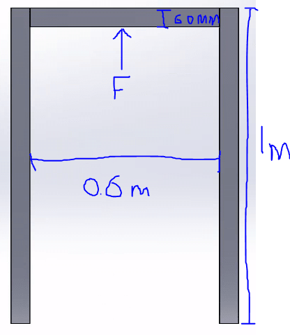
The beam would be welded to the side posts and those posts are fixed to the ground in this example. The cross section (not sure if it matters too much) is square box section.
The side supports also are cantilever beams. You solve this by working out the stiffness of each element, and then, the total stiffness. This is what strain energy method does. This is what FEA does, although on this problem, the matrices are small enough to be solved by hand.
You have to know the cross - section of each beam or column in order to calculate "I" moment of inertia , in order to plug it into the formula. Or in the case of the more exotic methods , computers will solve it based on the geometry of the cross section.
You must know how big the members are and what material they are made of in order to plug in "I" and "E" , the Youngs modulus.
I would go with Roark and Young , because their formulas were empirically tested by experimentation. If you want to use a computer, you could put the problem into an F.E.A engine , finite element analysis.
I would not use the distortion energy theorem, although that would be one way to get there. Keith
In my opinion using Castigliano , Deflection , Distortion Energy , Von-Mises is a little overkill … for this.
You would not use an atom bomb to kill an ant.
I think this one is a good exercise for paper and pencil
Make the simplest check by calculating the lower bound for deflection. Assume the posts are completely rigid and the beam is totally fixed to the posts at both ends. If the beam is loaded at the center (which appears to be the case in the sketch):
Deflection > F x L3 / (192 x E x I)
Where L = Beam Length
Chances are deflection calculated by more precise means will be slightly higher, but the same order of magnitude as the lower bound.
An example: Say lower bound deflection is calculated to be 2.0 mm, more precise deflection may be, say, 3.0 mm.
I have tried to use Roark and Young but I am struggling to find equations that are not in equilibrium and therefore cannot find the deflection. I think I will have to try another method
You need to find the moment at each end of beam, then find the deflection by superposition. The deflection must be equal to the simple span deflection due to force F, plus (or minus in this case) the deflection due to the end moments.
If the end moments are equal, which they are if F is at midspan, and the structure is symmetrical, then deflection at midspan due to end moments is ML2/8EI.
![[idea]](/data/assets/smilies/idea.gif "[idea] [idea]")