Continue to Site

Eng-Tips is the largest engineering community on the Internet

Intelligent Work Forums for Engineering Professionals

  • Congratulations SSS148 on being selected by the Eng-Tips community for having the most helpful posts in the forums last week. Way to Go!

How to calculate Working Load Limit (WLL) 7

Status
Not open for further replies.

arunmrao

Materials
Oct 1, 2000
4,758
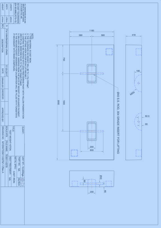
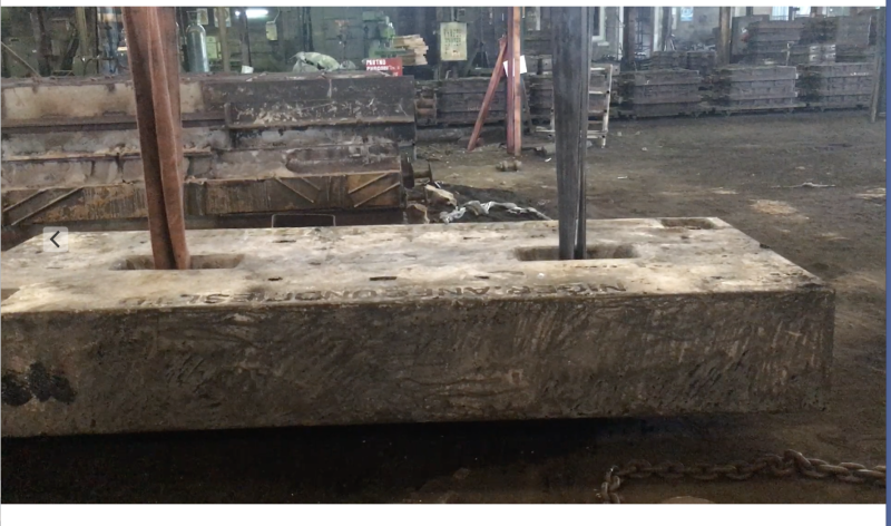
I am planning to cast a 10 ton test weight ( 3000mmlong x 1160mm wide x 418mm high). There are 2 lifting points with 45mm dia 600mm long 304 grade S.S rod. The exposed length of rod is 200 mm, under which a 6ton belt can pass.

I have been asked to indicate WLL at each of the lifting point. This is not my area of expertise and I seek your help.

I have used for my back of envelope, the following method :
Working Load Limit = Minimum Breaking Load / Safety Factor.

Safety Factor = 5

Tensile strength of 304 SS = 505 MPa =51.5 kgs/mmsq (approx)

Cross section area of round bar. = .785 x45 x45 = 1589.6 mmsq

AS the loading is in transverse direction and not the longitudinal ( along the length of the bar) , I factor the breaking load by 0.6.

Thus ultimate shear strength = 0.6 x UTS

In this case Ultimate shear strength = 0.6 x 51.5 = 30.9 kgs/mmsq.

Therefore Ultimate shear load or Breaking Load = 30.9 x .785x 45x45 = 49119 kg=. 49.119 tons

Thus WLL = 49.119/5 = 9.824 tons .

Our maximum loading at each point is 5tons for the design .


My question, is this simplistic approach acceptable or are there any fallacies in it. Please let me know, so that I can improve upon my design if necessary.

Thanks in anticipation and appreciate your time and efforts..

"Even,if you are a minority of one, truth is the truth."

Mahatma Gandhi.
 
Replies continue below

Recommended for you

A sketch to show the geometry would help.
I assume "6 ton belt" is a fabric sling or strap with 6 ton capacity?
 
Arunmrao:
There is actually quite a bit more to the problem than your quick calcs. would indicate. I have no gut feeling for working in MPa, kgs, mm units so I didn’t convert everything at this time to check your calcs., but your test weight is 9.84' long, 3.81' wide and 1.38' high, and in steel at 490 lbs. per c.f., that’s 51.36 c.f. and 25.17k. Then, the lifting lugs are 1.75" (45mm) round 304 SS bars, embedded into the casting mold, some distance and extending above the casting 200mm. The questions..., what vert. leg spacing for slings or hooks/clevises, etc.; does the casting have any tendency of shrinking away from the SS round during cooling, thus eliminating any bonding; alternatively, what’s the bottom detail, 2 large washers and nuts for bearing (10t/4 nuts = 2.5t each bearing point). Several things with the lifting lugs above the casting...., you will be lifting on them at an angle with your slings, thus there will be max. bending moment right at the casting top, a function of the sling loading and angle; and the variations btwn. fiber slings and hooks or clevises causes shear, bearing and bending in the lug itself, not just the simple shear you calc’ed., this is a function of the 1.75" bar dia., the dia. of the top 180̊ bend, the leg spacing and the size of the sling, hook, etc. Take a look at a good Strength of Materials or Theory of Elasticity textbook for chain link design, lifting eyes/lugs, eye bars, etc., also ASME BTH-1, “Design of Below-the-Hook Lifting Devices” is a very good guide for what you are doing. Finally, why SS round bars, why not a little larger carbon steel bars to account for some abuse and corrosion; also, a 3.25'x3.25' block by whatever length (shorter length) might ship and handle a little better. The deeper block will not swing and tilt as much in lifting because your lifting points aren’t perfectly centered about the block C.G.
 
Hi arunmrao

Please provide a sketch.

“Do not worry about your problems with mathematics, I assure you mine are far greater.” Albert Einstein
 
Thanks, I am providing a sketch of the test casting with lifting lugs for your suggestions and comments.Thanks once again in your interest to help me find a solution.
Screen_Shot_2017-03-17_at_08.58.32_dynhr9.png


"Even,if you are a minority of one, truth is the truth."

Mahatma Gandhi.
 
Hi again

The lifting pins will see bending stresses as well as shear stress and in addition the pins will generate a bearing stress against the cast iron block as it is lifted.

Another question is how are the rods inserted into the casting or are they cast in place?

“Do not worry about your problems with mathematics, I assure you mine are far greater.” Albert Einstein
 
They are cast in situ.

"Even,if you are a minority of one, truth is the truth."

Mahatma Gandhi.
 
Just from looking at it, I see the 60 mm of fragile cast iron above the inserted rods as the weakest/unpredictable link to resist the load.
What that edge around each rod is (plan view)?

"Engineering is achieving function while avoiding failure." - Henry Petroski
 
Hi

Perhaps I am missing something but the melting point temperature for cast iron is only about 100 degrees C less than that of stainless steel?

It might be better to forget the cast in pins and drill and tap two holes in the casting for lifting eyes.

Forgetting for a moment my above comments I would calculate the pins as simply supported beams and assume the span of the beam to be 600mm but I would also check the cast iron material above the pin for bearing pressure stress and pin breakout due to shear stress failure of cast iron.


see heading "strength of bolts under direct shear loading"

“Do not worry about your problems with mathematics, I assure you mine are far greater.” Albert Einstein
 
Hi arunmrao

So what's the outcome are they still casting in place pins or adding tapped holes?

“Do not worry about your problems with mathematics, I assure you mine are far greater.” Albert Einstein
 
Sorry, we are still going ahead with casting pins in place. However the 60mm is now 75 mm an additional 25% increase in meat !!

"Even,if you are a minority of one, truth is the truth."

Mahatma Gandhi.
 
What about the temperature of the molten cast iron coming into contact with the stainless steel I can imagine that this might be a problem.

“Do not worry about your problems with mathematics, I assure you mine are far greater.” Albert Einstein
 
1280C is the pouring temperature. By the time the metal rises from the bottom of the mould filling it gradually, there will be drop in temperature by at least 50C.

Thus we can have a temperature difference between molten metal and SS pin about 225-250C. Also using SS pin cast in situ is the industry practice .


"Even,if you are a minority of one, truth is the truth."

Mahatma Gandhi.
 
Hi arunmrao

Well I learnt something too, I didn't know it was an industry standard.
I have seen inserts in aluminium castings never in cast iron.

“Do not worry about your problems with mathematics, I assure you mine are far greater.” Albert Einstein
 
An update. I recently cast the test weight and using the lifting pins, was able to lift the weight. A picture of the same is provided.

Thanks all for your contributions.

Screen_Shot_2017-06-05_at_19.42.27_ovkgdq.png


"Even,if you are a minority of one, truth is the truth."

Mahatma Gandhi.
 
Hi arunmrao

Thanks for the update.

“Do not worry about your problems with mathematics, I assure you mine are far greater.” Albert Einstein
 
Status
Not open for further replies.

Part and Inventory Search

Sponsor