Eng-Tips is the largest engineering community on the Internet

Intelligent Work Forums for Engineering Professionals

How to consider the ellipsoidial head strengthing effect. 1

Status
Not open for further replies.

mechengineer

Mechanical
Apr 19, 2001
256
0
0
SG
Dear All,
Lifting_lug_n9flef.png

How to consider the ellipsoidal head strengthening effect on the shell where located the lifting lug when analyze the local stresses by WRC?
Thank you.
 
Replies continue below

Recommended for you

If you use a spreader beam and lift the vessel vertically the head would not have loading on it. This is the way you normally lift the vessel.

The horizontal plate connecting lug onto the head is for stability only, does not contribute lifting.

However, if you use chains or rope connected onto the lifting lugs with angles other than 90 degree and a single lifting point in the centreline above the vessel you will end up with forces on the lugs with force in horizontal. This will destroy the lug connections, do not use this type lifting.

So you do not need a WRC calculation for those connections on the head.

I hope I understood coŕrectly, and this post will be useful for you.
 
I do not think that is common, but I cannot say anything about your work practice.

If you look at your connection area the horizontal force will bend plastically the plate (lug) at the level to the horizontal plate connection or above whereever is weaker.

If someething happens you cannot explain it within structural codes logically and you will be liable.

Please review your work practice and use a spreader beam for lifting.
I understan thiis forces the height requirements for crane. But you do not have other choise.

Let us assume you have overcomed all the problems above and the lateral load from the horizontal gussets will be taken by the head.I can tell you I have not seen any calculatiion with a line load on the head. That does not fit any of WRC limitations. But you may have to run a FEA to show nothing wrong stresswise with the connection and deflections are under control.

Hope it helps.
 
I forgot to add;

The 60 deg angle pull of the coñnection will change the shape lug plate and there will be a new moment distribution will oçcur. The moment distribution will change cause rotation between lug platee and horizontal plate. This rotation will introduce moment in additioon to axial force on the horiizontal plate and its connections unless it changes the shape. The shape change may result of loosing resistannce to the axial force. In the end you will end up with lug angle change to become in line with the rope or chain.

This explanation may lòok like exaggerated but you may end up with this if plasticity starts. This may even end up with failure during the lifting.

Please consider this as a warning only.
 
You have a gusset running along the length of the lug providing strength and stability.
Therefore there is no need for the horizontal member. Typically the horizontal member is only applied when the lug is flat plate that is susceptible to bending. An appropriately sized gusset welded along the length of the lug removes the need for the horizontal member.
Having two stability members is a statically indeterminant structure that even FEM would struggle to provide accurate results (certainly with an elastic analysis).
The horizontal member is attached to the knuckle so WRC is not applicable.
 
I agree with all of the other posts. If you want to use the current lug layout, use a spreader bar. If you want to use a single point lift with 60 deg lift angle, rotate the lifting lugs and weld them on the head. Typically, we would use 3 or more lugs welded on the head if using a single point lift. WRC is quick, but it's not a great way to look at the stresses on the head from lifting; I recommend FEA and proven hand calculations instead.
 
Rotating the lugs isn't suitable for the tailing operation. A single point lift would be common for smaller vessel sizes with this arrangement. Using a smaller included sling angle would be recommended, however, everything can be designed for. Angling the lugs in towards the line of action would assist in reducing bending in the lug and prying on the shackle pin but doesn't help with lateral loading on the other components. When the shackles aren't loaded normal to the pin they need to be de-rated accordingly. For a large heavy vessel, I would agree that a simple spreader beam would be recommended for this lift arrangement.
 
We could, no doubt, definitively answer the question if it were not for all the stuff we don't know :)

Regards,

Mike

The problem with sloppy work is that the supply FAR EXCEEDS the demand
 
Sorry for late response.
Capture_cgjifl.jpg

My point is how to consider the ellipsoidal head strengthening effect for the lifting lug local stresses by WRC107 on shell. It may be sure that the ellipsoidal head strengthening effect is significient, if no the ellipsoidial head, thecylinder shall may be deformed.
Due to it is a replacement of existing vessel and space limited, so the preader bar is not applicable.

Thanks,
 
@TGS4, Your anwsers almost are correct. Yes, that is one option. But it is not what I want. Due to FEA is not widely used by pressure vessel manufacturers and cost cosideration, if it is possible, I seek a simple, approximate method to consider the ellipsoidal head strengthening effect by hand-calculation. Otherwise, I will ignore it that will be much more conservative.

Thanks,
 
It sounds like you are trying to use WRC for something it wasn't intended to do. FEA would take the geometry affects into the stress results, but you don't want to perform the analysis; so like you said, you just have to be conservative.
 
Such a method is not available. As CodyK says, you are trying to use a method well beyond what it was intended to be. Whether that is conservative or not is not possible to be known. You are treading into unknown territory.

Here's a simple warning - if you go down the path that you a trying to justify, and there were to be a failure, you would have significant liabilities. And your defense that you followed good engineering practice would not be valid. It is likely that your professional liability insurer would abandon you.

BTW, FEA is frequently used by pressure vessel manufacturers. Regarding the cost, please consider my above paragraph. Forget the commercial aspects for your company. Personally, can you afford a massive liability? Would you bet your family's house on this approach?
 
@TGS4, Ha, ha, your words are too serious. Anyway thanks your kind advise.
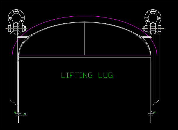
I know that currently nobody considers the ellipsoidal head strengthening effect for the lifitng lug whatever engineering practice, softwares or engineering books. Some case to increase the thickness ( or a bean support if possible) of the top shell course is just for the lifting lug. It is just a discussion here, I would not put it into my design if no solid theory basis and suceccesful engineering practice.
If you are a university student, it doesn't matter. However, if you work for a company, it won't be. You may not use the house to mortgage, but you may lose the job. A good design shall be correct, easy, simple and saving cost.
If it is really FEA widely used by manufatures, the design results often vary from person to person. The standardization of pressure vessel design with finite element may be another issue to be solved. It's a personal opinion only.

Thanks,
 
Mechengineer,

I do not want to get into conclusion immediately, but you seem to be you know what you are doing. In that case,

What is your purpose that you use this website, and take other’s valuable time?

Why you forget to respect to the people that giving their own time and advice you from their professional background?

We sometimes understand some people with little knowledge in English language but we ignore that after seeing their respectful wording. It seem you are not one of them. I hope I am wrong.
 
Status
Not open for further replies.
Back
Top