Eng-Tips is the largest engineering community on the Internet

Intelligent Work Forums for Engineering Professionals

  • Congratulations waross on being selected by the Tek-Tips community for having the most helpful posts in the forums last week. Way to Go!

How to convert FEA analysis into a material choice? 2

Status
Not open for further replies.

CharlesFrench

Mechanical
Nov 19, 2018
4
0
0
GB
Hi All,

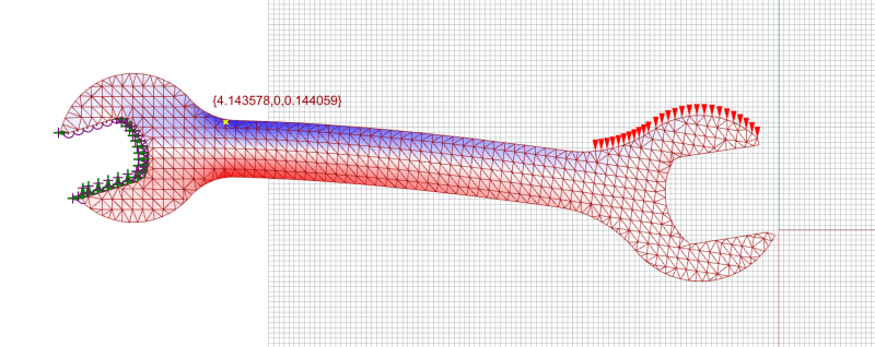
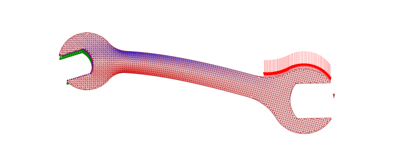
As pictured below, I have an FEA carried out on a wrench.

I've applied 20kN across all red arrows whilst fixing all green points.

The main output of the simulations is the first principle force stated in kN/m per mesh face, where compression < 0 and tensile > 0.

My question is; how does one convert this output into an material that is rated for these figures?
Does the above contain sufficient information to make an educated guess? If not, what am I missing?

I understand that ultimate tensile strength is rated in MPa, what does my conversion look like?

Thanks,
Charles


0_jmfvpu.png
 
Replies continue below

Recommended for you

this is probably a CAD-based FEA (with a whole bunch of things "hidden" for the user).

Charles,
Your FEA includes/assumes a material already (you should find what which material is used in the FEA).
You probably don't want to use normal force output ... you can (but you need to convert to stress, by dividing by thickness).
I won't restrain the curved portion of the wrench lug (ie, just the flats are in contact with the nut being turned).
Have you modelled with triangles, or TET (triangular pyramids), elements ? (not the best choice, for a bunch of technical reasons)
20kN sounds like a lot to apply (by hand?) ?
 
@TheTick

Current simulation is run on Steel S235, but I can see that if I select a weaker material such as wood my forces remain the same within 1%.
Am I right in thinking that the forces exerted on my model will be agnostic of material choice, providing material isotropic?

@rb1957

Thanks for your input, I'll address your questions;

First of all I'll correct my mistake, input is 0.09806 kN which equates to 10kg.

I'm using a parametric FEA tool called Karamba3d which is a plugin for Grasshopper & Rhino3D. I have full control over inputs/outputs.

This simulation outputs a maximum of 387.77 kN/m which if squared gives me 150371.35 kN/m2, I can convert this to MPa which give me 150.37 MPa.

My understanding is that if I select a material which has a ultimate tensile strength above 150MPa it'll be able to withstand my load?


As you can tell, I'm no FEA engineer so helpful comments over condescending ones are much appreciated! :)
 
"This simulation outputs a maximum of 387.77 kN/m which if squared gives me 150371.35 kN/m2, I can convert this to MPa which give me 150.37 MPa."

Um, no, you get kN^2/m^2 by squaring that result. Which does not make sense. You appear to be doing a 2D analysis, which might give results in form suggested....which you might then divide by the material thickness (which might be a small multiple of 1 meter) to get units of stress in the form of force/unit area.

Basic strength of materials classes, or even statics, should give you an idea, via hand calculation, whether your numbers make sense...did you do a hand calc?
 
To convert your normal forces to stresses, you need to calculate the actual force on each element.

Force Couple (kN/m)* Length (m) = Force (kN)

Once you have force on each element, you need to convert your force into a pressure (which is the same as stress) by assuming some thickness of material. Right now the 'face' of each element is a line between nodes. In order to determine pressure, you need to extrude this material so that each line becomes a planar face over which force is applied.

Force (kN) * Element Area (M[sup]2[/sup]) = Stress (kPa)

The force on each element is fixed, but the stress on each element is dependent on the thickness of that element- you can't calculate stress for a planar element.
 
with all due respect, you are playing with a loaded gun, but don't realise it. I do dislike FEA packaged with CAD software 'cause it enables people to model their structures (as you are doing) without any real understanding of what is involved. But it this case your FEA is so limited (only giving normal force) that you had to ask "wtf?"; this is fortunate (IMO) 'cause if it output stress you'd think "well done" without realising what is involved. You don't even know that somewhere you've defined (or the FEA defaults to) a material (though in this particular case it probably doesn't matter, because of the simple nature of the problem). By this I assume that you haven't really read the manuals, or have done the tutorials. Sorry, Charles; please learn some of the basic material first, even (shudder) wiki would help.

another day in paradise, or is paradise one day closer ?
 
No CF, changing material will significantly change the stresses because of things like changes of modulus and localized yielding.
Go back and figure out that your software is assuming.

= = = = = = = = = = = = = = = = = = = =
P.E. Metallurgy, Plymouth Tube
 
Your reaction forces will be substantially the same but internal stresses will change with material.

The fun secret of FEA is that all steel bends the same until yield stress is exceeded. In such cases, one can run any grade of steel, then select grade based on stresses.

I'm trying to be helpful, but if you don't wise up and stop conflating kN with kg I will have you flogged.
 
Given that it is a built in, probably free solver, one can assume it only does a linear solution (no local yielding). This kind of tool in the hands of untrained users is like giving a child a loaded gun.

----------------------------------------

The Help for this program was created in Windows Help format, which depends on a feature that isn't included in this version of Windows.
 
You can see the model post simulation which is color coded based on material utilisation. Where blue is tension and red compression.

I then find the maximum first principal stress vector (yellow point) and display the value above it in kN/cm2.

Given that most material Ultimate tensile strength is rated in MPa, I need to convert 4.143578kN/cm2 into 41.43578MPa.

Therefore if I select a material with an tensile strength rated above ~40MPa my wrench should be able to withstand the 10kg of force? This seems to simplistic?! Am I missing anything?

material utilisation: The utilization is calculated as the ratio between yield stress of the material and maximum Van Mises Stress along the shells cross section high.

0_jfam4x.png


Picture below is color coded based on First principal stress.

1_cv59ko.png


@jgKRI Thanks for correction and helpful comments, I've managed to find a kN/cm2 output instead of doing the conversion myself.
 
CharlesFrench,

You are showing a reaction force in which the jaws of the wrench all are located solidly. I would expect a clearance between the jaws and the nut, and a pair of concentrated reaction points. FEA is futile if it does not simulate real-world conditions.

--
JHG
 
why does the coloured mesh look different to the 2nd view (which seems to show a recess) ? Are you using 2D (planar) elements, or 3D solid elements ?

another day in paradise, or is paradise one day closer ?
 
@rb1957 Not sure what differences you're seeing but the top one is colour coded based on material utilisation and second on first principal stress. Both are the same mesh and setup. I'm using 2D elements.

I should also clarify that I'm not looking for a highly accurate result, rather a starting figure that that I can rate 50% above for an initial material selection and testing. The methodology of FEA conversion into material selection is really what I'm interested in. If anyone has and links to share on the subject that'd be much appreciated.
 
am I right in thinking that the body of the wrench is hollowed out, so that the cross-section is like an "I" ? (that's what I see in the two views in the last post.) How do you set the thickness of the 2D elements ?

I don't quite get "a starting figure that that I can rate 50% above for an initial material selection and testing.". One thing this is not "testing" is the jaw of the wrench. If the material is not steel, or something like it, then the nut will probably deform the socket before the body of the wrench fails.

another day in paradise, or is paradise one day closer ?
 
Agreed. You also may need to consider intentional misuse, depending on your application - for example, may users will apply a hammer to the free end, if the bolt is too stiff. Or use a pipe, or another spanner, locked onto the free jaw to increase leverage.
And as others have noted - the assumed fit of the bolt inside the jaws is too snug. In the real world, you have to deal with gaps due to damage, manufacturing errors, etc.
 
Status
Not open for further replies.
Back
Top