1) It seems that there are 2 bending moments in 2 different planes, so may I use this formula to find total S and compare with allowable compressive stress? S = -W/A +/- Mxx/Zxx +/- Mzz/Zzz
Yes, if the forces that produce the bending moments can act simultaneoulsy, then the stresses produced by the xx and zz planes would add by superposition.
2) What is the unsupported length of colum in this case? Total height of saddle? What is boundary condition? It's clamped+free or clamped+clamped?
I would say the unsupported length is the height of the side plate minus the thickness of the base plate since the base plate provides support for the vertical plate at the bottom. I would say the vertical plate is fixed at top and bottom but at bottom it can rotate slightly so to be extra conservative you can model it as fixed in all directions but a pinned connection that allows rotation in one direction.
3) Ok but what forces/moments apply to vessel wall? 2 moments above and weight of vessels?
In accordance with WRC 107 analysis you need to do the analysis for the actual Fx, Fy, Fz, Mx, My, Mz forces and moments present.
If the horizontal load is sideways perpendicular to the vessel then there will be no moments present at the connection point of the vertical saddle to the vessel. This is because any external moment load is resisted by either a compressive force on the far side connection point or a tensile force on the near side vessel connection relative to the force, which will just add or subtract from the weight compressive load. Therefore, at the connection point you would have a radial P load (which includes the moment load) and a sideways shear load due to the horizontal force (divided by two since it is shared by each connection point).
If the horizontal load is axial along the longitudinal axis of the vessel, then the moment load is not resolved into tensile or compressive forces and does not add to the radial P weight load in a WRC 107 analysis. In this case you would have a radial weight load P due to weight of vessel plus a moment at each connection due to the external horizontal load (divided equally between the two connections) and a horizontal shear force due to the horizontal load (divided by two) at each support
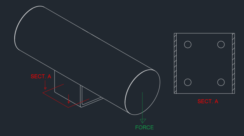
4) I don't know any external loads...but weight acts to the base plates through narrow lateral strips, so there are at least bending moments in the baseplate. But I don't know how to check it because base plate is "fixed" by 4 bolts in the middle acting like clamps??
You would need to provide a sketch of what you are talking about here.
Note that the analysis here for the support itself is very similar to an analyis for a skirt support for a vessel as most of the same dynamics are involved. Attached is a handbook chapter on this type of analysis.