Hello everyone,
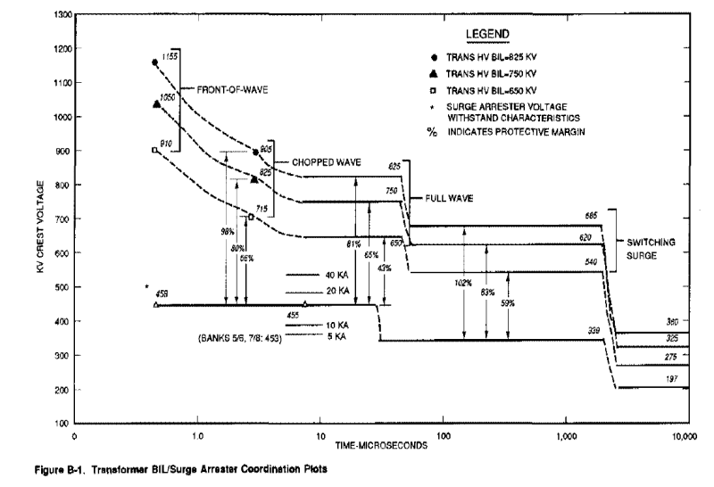
I'm trying to create a transformer insulation - surge arrester protective level coordination plot similar to the one below. My questions are:
a. Where do i find the duration of Surge Arrester Front of Wave (FOW), Lightning Protective Level (LPL) and Switching Surge Protective Level (SPL)? I only see the current impulse waveshapes from the manufacturer's data.
b Where do i find the duration of insulation levels for the transformer.
I already have the calculation for the protective margins but stuck on replicating the plot below. Thank you in advance for your responses.