Eng-Tips is the largest engineering community on the Internet

Intelligent Work Forums for Engineering Professionals

  • Congratulations waross on being selected by the Tek-Tips community for having the most helpful posts in the forums last week. Way to Go!

How to explain this singularity?

Status
Not open for further replies.

bojoka4052

Mechanical
Oct 8, 2021
108
0
0
NO
I have a wall that is subjected to water pressure, and in the corner of the structure I get this singularity. My coworker told me it wont be a problem in real life. I was wondering how could I explain to someone that even though its red (forces above the limit in the red area), its okay?

1_czjczx.jpg


Edit: Its a 2-D shell element model.
 
Replies continue below

Recommended for you

Sharp corners are one of the most common causes of singularities. In real life, there would be a small fillet in this location and it should help with the issue if you model such a fillet. You can also include plasticity to see how this region will yield.
 
Math models can have corners with infinite curvature - the radius is zero. Actual parts cannot do that as even at the atomic level the atoms aren't sharp points.

A better explanation is to replace that corner with a few elements that conform to a small, but realistic radius, and present that analysis to them as well. This would show that the stress concentration is much lower than the sharp corner predicts and gives a cost of doing that additional modeling and analysis time vs the amount of information gained. It small for one case, but if multiplied by 10,000 cases that time and cost increase.

It may also be valuable to do that a few times to see just how sensitive the design is - perhaps the material is so notch-sensitive that it requires a radius in that area to prevent crack initiation. Gain enough experience doing this and you will begin to recognize when the extra effort will pay off.
 
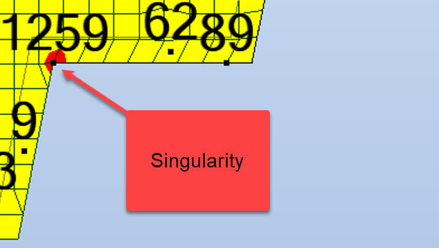
First let us consider singularity in mathematics. The singularity of mathematical function is point at which the function's value can not be defined or in other words value approaches infinity. Take f(x) = 1/x. The value of f(x) at x=0 is infinity or cannot be defined and the function is called singular at x=0. Similarly, now consider the values of stress at point. (Its different from stress at point to find out stress tensor components.) As the area approaches zero (consider point as nearly zero area) stress values tend to infinity. At the sharp corner, the resistance to the stress is concentrated at a corner point and hence the stress values are higher than adjoining area.

In reality, we cannot make perfect corner or anything that is perfectly round, square, flat etc. Some finite radius will always be present at corner and finite area resist the stresses at corner and hence the stress will be finite in real structures. Discretization/meshing introduces singular points in our FEA model (which is nothing but approx. mathematical model of real structure) which mathematically produces infinite or higher stress values.
 
linear model ? ... so localised plasticity. Possibly a neuber calc would modify the linear model stresses to real plastic material.

(as others have posted) is there not a radius in the real world ?

another day in paradise, or is paradise one day closer ?
 
What material is your model based on? Steel will yield, concrete will crack. If it cracks, will that be an issue since it is water involved?

Thomas
 
Dear Bojoka,
People use the phrase "singularity, you can forget it", but is very important to put attention to peak stresses, not simply forgeting, very dangerous!!.
Others say "in ductile materials the local stress concentrations can be ignored, and then it is permissible for the stress to exceed the material yield stress".
Well, we have do demostrate it: the way I run always is to perform nonlinear analysis and prove by calculation that the areas of local plastic deformation associated with stress concentrations are sufficiently small so as not to cause any significant permanent deformation when the load is removed.
peak-stress_rb1xwd.png


But please note "give me a point, and I will broke the part by fatigue". So the above depends of the material type and the load type, with alternate loading the only way to prevent failure is to design using a Factor of Safety (FoS) well bellow of yield stress of the material, a FoS=1.1 is useless, probably you will need values of 4 & 5 minimum.

Also other important point: "The Finite Element mesh should be fine enough & with the best quality to accurately predict the actual peak stress at the features". Coarse mesh is not valid at all.

In summary, you have the answer in your hands: run nonlinear analysis.

Best regards,
Blas.

~~~~~~~~~~~~~~~~~~~~~~
Blas Molero Hidalgo
Ingeniero Industrial
Director

IBERISA
48004 BILBAO (SPAIN)
WEB: Blog de FEMAP & NX Nastran:
 
Status
Not open for further replies.
Back
Top