Continue to Site

Eng-Tips is the largest engineering community on the Internet

Intelligent Work Forums for Engineering Professionals

  • Congratulations cowski on being selected by the Eng-Tips community for having the most helpful posts in the forums last week. Way to Go!

How to find the thickness of these walls?

Status
Not open for further replies.

bojoka4052

Mechanical
Oct 8, 2021
108
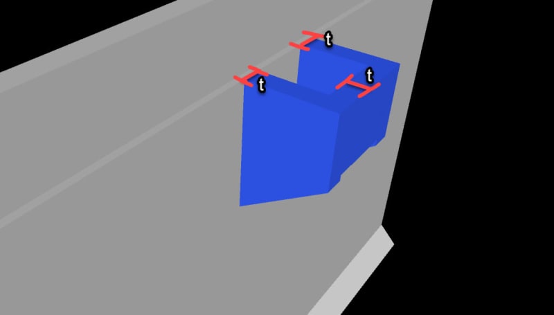
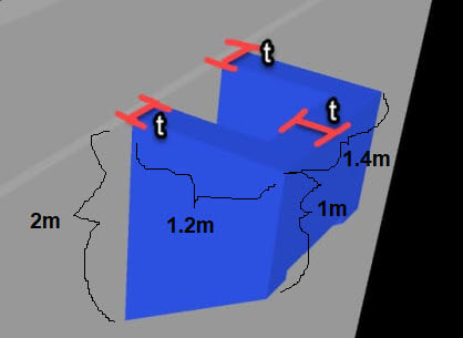
I have this little concrete piece attached to a vertical wall, for which I need to find the thickness "t", which is the same for all the walls that make up the highlighted structure:

1_xgrnrb.jpg

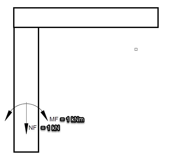
The only information I have is the moment and normal force that it will have to carry, and that the reinforcement will have to be approximately similar to a fixed cantilever beam:

2_qojlq5.jpg


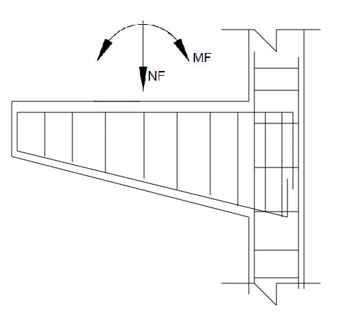
To find thickness of walls, where should I start? Should I find the necessary reinforcement to carry the load, and then adjust the thickness of the walls accordingly so that the reinforcement fits? Are there any examples of this, because I could not find it online. It does not have to be exact, I can do with a rough estimate.
 
Replies continue below

Recommended for you

It's hard to say without knowing the dimensions and loads. Is this thing sticking out 1 ft or 10 ft?

Assuming it's not small, I'd start with whatever thickness is required to fit the reinforcement in there. That's probably in the ballpark of 8 in. thick, but you need to sketch it out for your bar sizes, spacing, and clear cover.
 
We can assume the load is 1kN and 1kNm, and its sticking out 1 m or 1 ft, whatever dimension you prefer to be the easiest. So calculate necessary reinforcement and then adjust thickness accordingly?

I was thinking of just finding previous hand calculation examples on concrete corbel design to find necessary reinforcement and then find thickness of walls.
 
I have some questions and suggestions for you:
1. Why are you making a concrete corbel that is hollow? Make it solid - there is no point in attempting to save material when using a strut-and-tie model, since it will only complicate the calculation and still not guarantee that excess deflection of the "corbel walls" does not occur.

2. Why have you drawn a moment in the loading diagram? The load from a part placed on top of the corbel will be vertical and horizontal force, i.e., normal force and shear force, from the deadweight of the structure and the (code-specific) minimum horizontal progressive collapse tie force, respectively. These force components may be designed against using the strut-and-tie models for corbels found in the literature.

Remember that external moments and internal moments are not the same thing.

PS. If this corbel is supposed to carry some type of crane (you mentioned that in another post in this forum earleir this week), you may also consider making the connection a steel structure that is bolted into the wall. Tall and heavy cranes are most often carried by a braced steel frame, and not by concrete walls.
 
Centondollar, this is how the crane details are given to me; the loads are not 1 kNm and 1 kN but otherwise this is what im working with:

1_lzookr.jpg


And these loads have to be inserted into the structure seen in the first drawing, so I need to find a wall thickness big enough to carry this moment and normal force. The way I was thinking of doing it is to find whatever thickness is required to fit the reinforcement in there, and then make it slightly thicker just to be safe.
 
I've only got a little bit of info on Corbels, but I hope this old study slide helps a little.
Corbel_Basic_Info_orkgc9.jpg


"We can assume the load is 1kN and 1kNm, and its sticking out 1 m or 1 ft, whatever dimension you prefer to be the easiest." This is a silly statement. Loads and dimensions matter. If you are not provided the forces you have to figure them out based on the geometry and equipment it supports. We all deal with clients that are clueless about the data we need. If you want help for the corbel design start with an appropriate sketch.
 
The dimensions are given below, and I need to find thickness "t". I dont know how the loads from crane will be distributed on this structure, I dont think I have enough information, so I just have to make assumptions for worst case.

1_cobjfi.jpg
 
That is one step. How many tonne or ton is the crane? Presumably you know the spacing of the corbels and the span of the crane? From those numbers you can start to nail down the magnitude of the problem. As an engineer you sometime must say no, I cannot design this based on the information I have.
 
Why do you write "the dimensions are given below"? You are the engineer - you decide the dimensions, and as an engineer, you should know that strut-and-tie design of corbels does not involve thin walls! Make the corbel solid and start the investigation by thinking about the problem parameters, including those mentioned by user "Brad805".
 
What about this; if I can model the structure in FEA programme, and find the point with highest stress, since the stress = force/area, can I just base my thickness on this area? Not sure at which point I should look at the stress though.
 
That would not work, for many reasons that should be obvious to anyone familiar with the behavior of reinforced concrete. Furthermore, "stress = force/area" is only valid for a simple bar model with axial tension or compression; for more complicated loading and more complicated models (e.g., beam, plate, shell, solid), there exist many stress components and choosing the correct ones (or a combination of them, such as Tresca or von Mises stress) requires understanding of mechanics of materials.

I suggest that you do not model anything in an FEA programme before you learn the fundamentals.
 
Tell me you’re not attaching this to an existing wall…?

Assuming its all reinforced concrete, make the whole thing solid and design it as a normal corbel of which there are countless design examples within textbooks.

“No engineer shall be more clever than is necessary!”
 
These threads would be much more entertaining and interesting if we could get an update on the outcomes in 6months time. Assuming nobody dies of course... [bomb]


(That said with a post history like THIS I state to think he is a student pretending to be an actual engineer.)
 
centondollar said:
That would not work, for many reasons that should be obvious to anyone familiar with the behavior of reinforced concrete. Furthermore, "stress = force/area" is only valid for a simple bar model with axial tension or compression; for more complicated loading and more complicated models (e.g., beam, plate, shell, solid), there exist many stress components and choosing the correct ones (or a combination of them, such as Tresca or von Mises stress) requires understanding of mechanics of materials.

Thank you, it made no sense when I looked at it in my FE model. I think regular concrete corbel design is the way to go.
 
Status
Not open for further replies.

Part and Inventory Search

Sponsor