Continue to Site

Eng-Tips is the largest engineering community on the Internet

Intelligent Work Forums for Engineering Professionals

  • Congratulations KootK on being selected by the Eng-Tips community for having the most helpful posts in the forums last week. Way to Go!

How to get the size of bolts to mount a steel section to the concrete wall? 11

Status
Not open for further replies.

StathPol12

Aerospace
Jan 4, 2016
19
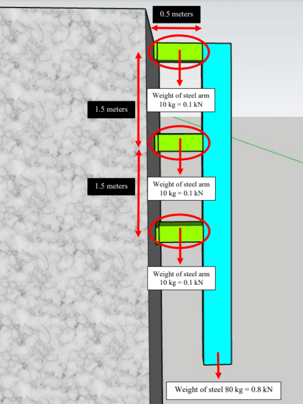
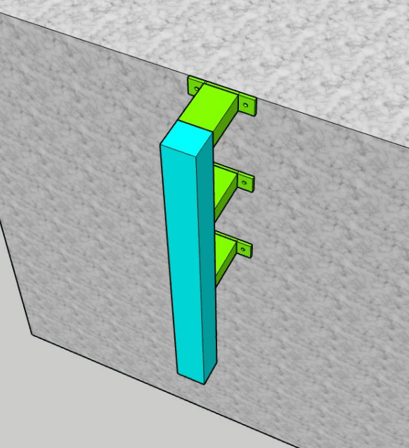
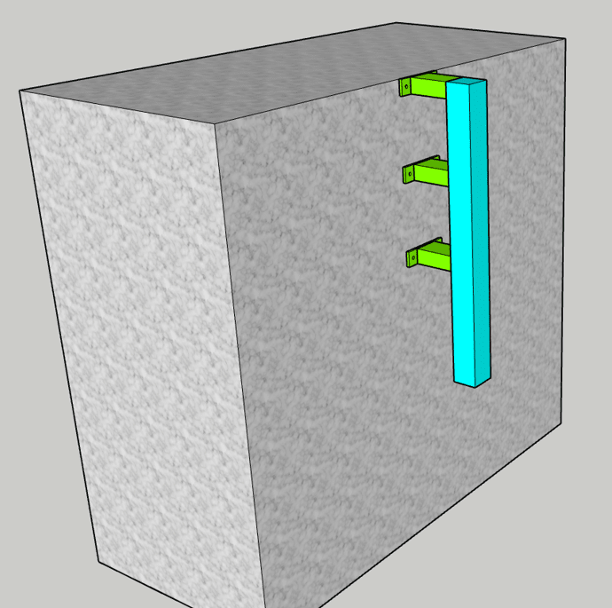
I aim to mount a rectangular, long, steel section to the wall, using 3 steel plates. The 3 steel (arm) plates will be welded to the steel section to the one side, and then use bolts to mount them to the concrete (rigid) wall. What size of bolts shall I use?

1_aaerxp.png
3_wbwcs3.png
1_a7q4eb.png
 
Replies continue below

Recommended for you

Looks like it's going to be nearly total shear load on the bolts, provided you don't go trying to pull it away from the wall or hang another load off it. Just the weight of the steel, right?

If that's the case your shear stress = weight ÷ total cross sectional area of all the bolts, which must be less than the bolt material's allowable shear stress. If the steel weighs 300 lbs and if one bolt has an area of 0.5 in2 and you've got 6, the shear area is 3 in2, so shear stress is 300 lbs/3 in2 = 100 lbs/in2.

What kind of bolt material will you be using?

--Einstein gave the same test to students every year. When asked why he would do something like that, "Because the answers had changed."
 
I feel like 1503-44 is doing you a disservice. There is likely more load on this than just the dead load of the steel.
This is pretty basic stuff and this is not the place to get engineers to design things for you. I would consult with a local structural engineer.
 
StathPol12 said:
What size of bolts shall I use?

The size your structural engineering consultant advises would be the best place to start.
 
Well I am only a PE Structural (Ret.). Given that the loads are posted, and I did ask for those to be confirmed, and they are "structurally" next to insignificant, including the 40 kgm moment that adds a 13kg tension, 6.5 kg per bolt, that's pretty good service IMO. And he doesn't have to wait 2 weeks for a £5000 FEA analysis either. Are you going to add 1000kg tension on each bolt for no apparent reason, or something?

Given the posted loads, I'm sticking to that opinion. I've got wooden shelves on the wall with more load than that thing. This is DIY, not PE territory.

--Einstein gave the same test to students every year. When asked why he would do something like that, "Because the answers had changed."
 
1503-- even given the information noted, it would be prudent to note two things:

1. When anchoring to concrete as shown, it is most commonly the concrete that limits capacity, not the shear capacity of the bolts.

2. If the sketch is representative, with the top row of bolts very near a free edge, observations #1 and and the tension you note become even more impactful.
 
Pullout load on the top two bolts is the only critical question that comes to mind. Failure will not be from bolts themselves either. In tension, shear, or combined stress. Friction on whatever inserts are used to keep them in the wall is the only critical point to consider. I can imagine that the bolts will not be embedded in the wet concrete. Do we really need a PE seal on this? Wow. Definitely OTT.

6 bolts are there. If the top two somehow rip the concrete out, the next two down will pick up the, what now a 25kg tension load ÷2 = 12.5 whole kilos in tension? Let's double the load to be safe. 25 kg? My microwave shelf has more pullout than that. The bolts are only 3cm apart. 4mm diameter screws with plastic inserts behind ceramic tiles. The bottom screws are not even tight, as they are only there for stability.

--Einstein gave the same test to students every year. When asked why he would do something like that, "Because the answers had changed."
 
1503-44 said:
And he doesn't have to wait 2 weeks for a £5000 FEA analysis either

It is interesting that you think an engineer is going to do a $5,000 FEA analysis of this.
 
I think so? No. I said it's DIY. But it does sound to me like (at least some of) you all do.

--Einstein gave the same test to students every year. When asked why he would do something like that, "Because the answers had changed."
 
FEA? No way. A 30 minute proper concrete anchorage calc (I'm assuming post-installed into an existing wall)? Absolutely.
 
I kind of think an engineer should be able to something so simple without any calculations at all. None. 0 Nada. Maybe it's an experience thing. I'm comfortable. Do your calcs if you need to.

--Einstein gave the same test to students every year. When asked why he would do something like that, "Because the answers had changed."
 
I'm confused, didn't you start with calculations at the top of this thread?

A quick anchorage calc like Lomarandil said is not splitting the atom, it's going to the Hilti book and applying the correct factors. That's kind of hard to do without looking it up at all unless you memorized all the charts.

Usually when an engineer is going to do something without any sort of calcs it's simple things like how far can a 2x8 span generally before we need to bump it up to 2x10s, things like that.
 
There's a lot off with this thread. For one what the heck is this thing? I doubt it's there to just support itself and this weldment doesn't look DIY to me. Looks like someone wants free engineering without having to give all the relevant information. Also if 1503-44 is sooo experienced why are you spouting about V/A calcs and friction on inserts, that's not how I or any engineer I know design anchorage in 2023.

IF and big IF this is only supporting the loads shown it works with a pretty nominal anchor that wouldn't require a calc. Though you'd need a pretty small anchor to make the top work for edge distance.
 
For what it's worth, the OP has been a member for about 9 years. Not real active, and the posting history doesn't make a lot of sense, but they didn't just show up today for free engineering.

And I wouldn't provide guidance on this because the information is likely incomplete. All that's given are self weights. That's great, but I seriously doubt this thing will be mounted and not used for anything or affected by any environmental forces. It's either worth having an engineer design or it's not. If it is, it should be done by a qualified individual being paid for their work. The OP came here, to a bunch of engineers, so they must feel it's worth having an engineer design it...
 
At the end of the day even if these are the only loads, its not exactly a child's play thing. If the anchorage were to fail the falling weldment could seriously injure someone. Simply designing the bolt for shear and selecting the diameter from that is just one step required for sufficient concrete anchorage design. You have concrete failure modes to consider that are a function of the concrete wall construction, anchor type, and post-installation technique.

I feel that 1503-44's response in general answers the question of what size bolts do I need, but sure the OP must have more questions, what type of anchor, how long? post installation procedure??

Post installed anchorage in general comes with several caveats that need to be well understood. Proper installation technique is one of the largest factors effecting anchorage strength. In the US continuous special inspection of anchorage techniques would be required for this horizontally mounted anchorage. Although the final results of the design may seem mundane or even trivial, much caution and care should be exhibited using post-installed anchors.

But then again, OP never said if anchors are going to be cast or post or really any info pertaining to the wall itself.
 
I can see I'm going to have to hire an independent consultant to check my 75" TV extended wall bracket anchorage.Anything in the code about TV brackets. Somebody could get killed. [shadessad]

Oh. I get it. You guys are just winging me up. I really fell for it.
The really important question here is why are the arms drawn in green and the column blue?

--Einstein gave the same test to students every year. When asked why he would do something like that, "Because the answers had changed."
 
Can you use a clip angle at the top to support it and then add a couple of bolts, down the length just to keep it in play. Whenever I design these things, I generally use one connection to support the loads, and the others just to keep it from wobbling.

-----*****-----
So strange to see the singularity approaching while the entire planet is rapidly turning into a hellscape. -John Coates

-Dik
 
I farm these out to engineering firms - for the purpose of getting a stamped design to satisfy the building code inspector. If I have questions about any part of the assembly I ask for a copy of the design report.
I expect to see things like a freebody diagram shewing how the anchor loads are determined.
The matching info showing how the anchor is determined, usually a catalog table from one of the suppliers of concrete anchors, and so on. this might include references to structural codes like ACI or ASCE. I have occasionally rejected design reports for insufficient attention to the details for example.

If the loads are known the anchor capacity can be found in a table in the fastener manufacture's catalog or website. More example information here.
Anchor embedment and distance to the edge can be more important than diameter. I would find the anchor with the worst load case, then use that size for all anchors.
 
The OP needs to define the purpose of this thing, and any applied loads, and the environment it will be in. Until then, we are just guessing on sizing.
 
Passing the buck on to Red Head or Hilti on-line calculators seems reasonable in this instance. Make some conservative assumptions and move on.
 
Status
Not open for further replies.

Part and Inventory Search

Sponsor