-
1
- #1
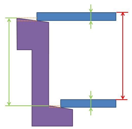
Can someone give me some help about handing draft angles in a tolerance analysis. Attached is an image of three parts. The two blue parts are mounted to the purple part on faces which are drafted. I know all the green dimensions and associated tolerances, but I would like to establish the tolerance stack up for the red dimension. Is it normal to consider the distances between the dashed lines caused by the draft angles or is this usually ignored. If it is included the analysis becomes quite complex, having to consider tolerances of the draft angles as well as horizontal positions of the blue parts. I would just like to understand if it is standard practice to include this level of detail.

Thanks

Thanks
