Eng-Tips is the largest engineering community on the Internet
Intelligent Work Forums for Engineering Professionals
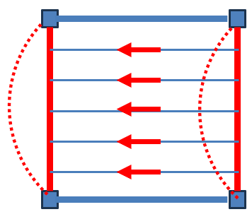
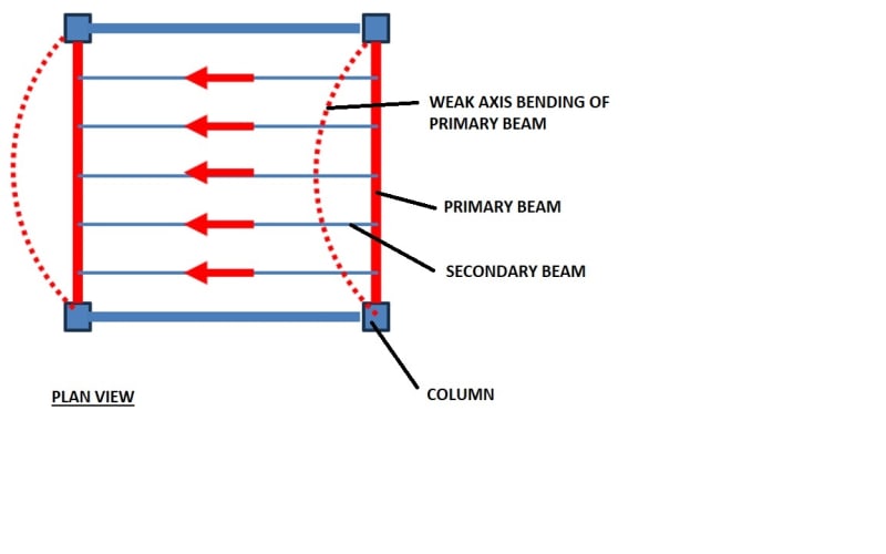
How to Increase Minor Axis Bending for Rolled-H section 1
- Thread starter MK_0202
- Start date
Similar threads
- Locked
- Question
- Locked
- Question
- Locked
- Question