Continue to Site

Eng-Tips is the largest engineering community on the Internet

Intelligent Work Forums for Engineering Professionals

  • Congratulations cowski on being selected by the Eng-Tips community for having the most helpful posts in the forums last week. Way to Go!

How to measure hole diameter?

burnswt

Mechanical
Apr 28, 2025
4
Situation:
I have an assembly made up four layers of different material laminated together, the resultant thru screw clearance holes are toleranced like this: 1745847825932.png

Datum A is the flat bottom of the plate (perp to the thru holes)
Datum B is a locating hole pep to A
Datum C is a slot aligned with B and perp to A

I have created a functional gage to check the 10 thru holes sized at 0.152" + (extra to account for gage stack up)

The four layers are often shifted relative to each other, resulting in a "tilted" thru hole
The assembly sometimes fails GO/NO-GO gage check at the small size
The assembly usually passes the functional gage check
Lets assume that the holes in the four layers are at the maximum size and the relative locations are assembly process limited

Questions:

If the part passes the functional gage check for the VC then does the diameter even matter?
How do I properly measure and report the diameter? Is it as simple as the largest pin that will fit thru the assembly, regardless of tilt? Or, should the reported diameter be the largest pin that will fit while perpendicular to datum A (see picture of cross section below)?
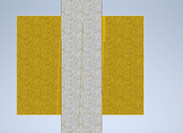
1745847486288.png
 
Replies continue below

Recommended for you

For the purposes of statistical process control you want to know the variation in the maximum unoriented hole size, the maximum oriented hole size, and the variation in the position. This will tell how good the process is.

For proving the part only the maximum unoriented hole size and the ability to accept the Virtual condition True Geometric Counterpart/Physical Datum Simulator. That is - that the hole is not oversized and that the hole will accept (if properly designed) the mating fastener.
Thank you.

How about the minimum unoriented hole size? If the thru hole does not accept a 0.166" pin (un-orientated, min size pin), does this violate the drawing?
 
Use "Go" and "No Go" gages to check. The gages need to be perpendicular to datum A.
 
Situation:
I have an assembly made up four layers of different material laminated together, the resultant thru screw clearance holes are toleranced like this: View attachment 8784

Datum A is the flat bottom of the plate (perp to the thru holes)
Datum B is a locating hole pep to A
Datum C is a slot aligned with B and perp to A

I have created a functional gage to check the 10 thru holes sized at 0.152" + (extra to account for gage stack up)

The four layers are often shifted relative to each other, resulting in a "tilted" thru hole
The assembly sometimes fails GO/NO-GO gage check at the small size
The assembly usually passes the functional gage check
Lets assume that the holes in the four layers are at the maximum size and the relative locations are assembly process limited

Questions:

If the part passes the functional gage check for the VC then does the diameter even matter?
How do I properly measure and report the diameter? Is it as simple as the largest pin that will fit thru the assembly, regardless of tilt? Or, should the reported diameter be the largest pin that will fit while perpendicular to datum A (see picture of cross section below)?

View attachment 8783
great questions, however I have a question as well, are the holes being match drilled.
or are they being drilled indepently.
and what is the size of diameter.
you quoted screws so I assume small fasteners.

reason when assembling 2 or more components it is important to keep them in line. either by match drilling or precise enough with tight tolerance. with constant
drilling such as a drill jig or precision machine. fixturing will have to be rigid.
and 10 percent of the tolerance.
now to answer your question!
if standard deviation is important ! as Dave stated. an independent virafication will be required. and if I may suggest, it will be important to keep the 4 components as a match set.
use go and no go pins to verify hole size.
that is and can be an independent inspection.
yes it is important. change hats here.
I would on purposely hole the holes on on high limit. as a manufacturer
not a concern for the design.
maintaining MMC .
what is functional gage, it's purpose is to verify acceptance. a d secondly it will assemble.
on the inspection report it will be listed
will the as the tolerance in the drawing
and as acceptable. inspected with gage.
how the gage itself designed is an other matter.
on top of my head without deep analysis I would simulate assembly.
I am forgetting specifications but depending on the spec, per the lot size, only a sample is required.
 
Use "Go" and "No Go" gages to check. The gages need to be perpendicular to datum A.
So to prove the part to the drawing, we would have to use Go and No Go gages held perpendicular to datum A; not just free insertion of the gages into the part?
 
great questions, however I have a question as well, are the holes being match drilled.
or are they being drilled indepently.
and what is the size of diameter.
you quoted screws so I assume small fasteners.

reason when assembling 2 or more components it is important to keep them in line. either by match drilling or precise enough with tight tolerance. with constant
drilling such as a drill jig or precision machine. fixturing will have to be rigid.
and 10 percent of the tolerance.
now to answer your question!
if standard deviation is important ! as Dave stated. an independent virafication will be required. and if I may suggest, it will be important to keep the 4 components as a match set.
use go and no go pins to verify hole size.
that is and can be an independent inspection.
yes it is important. change hats here.
I would on purposely hole the holes on on high limit. as a manufacturer
not a concern for the design.
maintaining MMC .
what is functional gage, it's purpose is to verify acceptance. a d secondly it will assemble.
on the inspection report it will be listed
will the as the tolerance in the drawing
and as acceptable. inspected with gage.
how the gage itself designed is an other matter.
on top of my head without deep analysis I would simulate assembly.
I am forgetting specifications but depending on the spec, per the lot size, only a sample is required.
My questions are not specific to the example shown, it was just an example I picked.

I really want to know the correct way to measure or gage hole size to say: this part meets the drawing. There's debate that the hole size should be evaluated as the max size cylinder (gage pin) perpendicular to datum A; the other argument is for the max size cylinder that the hole will accept regardless of orientation.

In practice, I agree with Dave:
"For proving the part only the maximum unoriented hole size and the ability to accept the Virtual condition True Geometric Counterpart/Physical Datum Simulator. That is - that the hole is not oversized and that the hole will accept (if properly designed) the mating fastener."

And the min diameter doesn't need to be gaged because we ensured the VC is not obstructed meaning the mating fastener will always fit.
O OK, I recommendation on the gage the pin should be no go, the gage should restrain to the datums, verify acceptance to mmc. The hole should be verified independently. Go and no go
 
The gage pin should be oe allow minimum hole diameter. Re iterate gage should be held with or by the datums.
 
Hi, burnswt:

Yes. You just need to make two sets of gages. Each gage is made of a plate with a pin. The pin is located at the BASIC dimensions from datum feature B and C. You will need features on your gages to simulate datum B and C. If your parts fit both the gages, then your parts are good. It does not matter how many layers of laminations. There are examples in ASME Y14.5-2018 standard.

If you do free insertion of the gage pins into the part, it will only check size of the hole rather than its position.
 
Thank you.

How about the minimum unoriented hole size? If the thru hole does not accept a 0.166" pin (un-orientated, min size pin), does this violate the drawing?
It does, but it also fails the virtual condition boundary and would be redundant. Besides, that value will be the maximum hole size for that hole. If the maximum hole size is smaller than the allowed minimum size, it fails.

Where life sucks is if the hole isn't particularly round. Like if it is slotted then it might still prevent a maximum size pin from entering but still exceed the allowable maximum in the direction of the length of the slot.
 
O OK, I recommendation on the gage the pin should be no go, the gage should restrain to the datums, verify acceptance to mmc. The hole should be verified independently. Go and no go
I stated it wrong should be go size
 
Hi, burnswt:

Yes. You just need to make two sets of gages. Each gage is made of a plate with a pin. The pin is located at the BASIC dimensions from datum feature B and C. You will need features on your gages to simulate datum B and C. If your parts fit both the gages, then your parts are good. It does not matter how many layers of laminations. There are examples in ASME Y14.5-2018 standard.

If you do free insertion of the gage pins into the part, it will only check size of the hole rather than its position.
you are incorrect about multilayer parts.
if the holes are not coordinated. there will be interference. that's why on aircraft bodies several details of two or more are match drilled. . rookie mistake
 

Part and Inventory Search

Sponsor