Eng-Tips is the largest engineering community on the Internet

Intelligent Work Forums for Engineering Professionals

  • Congratulations waross on being selected by the Tek-Tips community for having the most helpful posts in the forums last week. Way to Go!

How to mesh for crack propagation? 2

Status
Not open for further replies.

Gabriel Coelho

Mechanical
Apr 26, 2020
10
0
0
BR
Hello everyone,

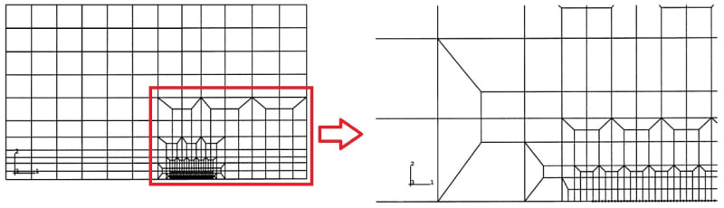
I would like to know how to make a mesh like the one the figure for crack propagation. It is very used in several research pappers and in the book of T.L. Anderson (Fracture Mechanics) it is called Cell Mesh, but I could not find any tips on how to perform it on Abaqus.

The more refined region is where the crack will be located and where the stress-strain resolution should be more accurate and there is no need to be so refined away from this region. My doubt is how to make this transition between fine/coarse mesh so structured and apparently using Structured Quad Mesh Control (please, correct me if I am wrong).

Thanks in advance for the help.

Sem_t%C3%ADtulo_d8qcha.jpg
 
Replies continue below

Recommended for you

You will definitely need several partitions with different seeding levels. Tie constraints between regions with very different mesh sizes may also help. It’s also possible to manipulate elements/nodes individually using Edit Mesh toolset but these options are not as complex as in some advanced meshers.
 
I had a similar problem. I was asking myself how on earth did this people do this kind of mesh.

So, my solution was to partition the region of interest exactly as you see in the images and mesh it with single element. With this you should be able to duplicate the mesh.

I would also suggest you to generate a python code that can do partitioning and meshing for you.
 
Thanks for the anwser, FEA way and GreenElmo!

Wow, it seems like a lot of trouble to do that everytime I need to simulate crack propagation, specially if the geometry is complex.

Have any of you tried Tie Constraint? The refined region to be the slave one and the coarser region to be the master one? Would that affect somewhat the displacements?
 
Abaqus can automatically tie incompatible meshes if you accept this option when prompted during meshing. You can also create tie constraints manually (master should have coarser mesh). That’s a great option to ensure continuity of results in case of incompatible meshes.
 
The meshing problem I had wasn't related to the crack but a different contact problem. So, I did not actually do much crack propagation in 2D models but I did in 3D. Based on my experience, I can say tie constraints change the crack behavior slightly. In my simulations, there were some cases where the crack offset 1 or 2 elements. I did not have any major problems with my results.

So, if you are not going to validate your results experimentally and will use the same concept in other models, I do not think using a tie constraint will give you a problem. In this case you will just compare the trends between your simulations.

You can also run a set of test simulations with and without tie constraints to see if there is a huge difference.
 
Status
Not open for further replies.
Back
Top