Eng-Tips is the largest engineering community on the Internet

Intelligent Work Forums for Engineering Professionals

how to model a 1/4" bsp external and internal thread for 3D Printing?

Status
Not open for further replies.

blohsg

Mechanical
Jul 17, 2007
5
0
0
US
Hi Everyone,

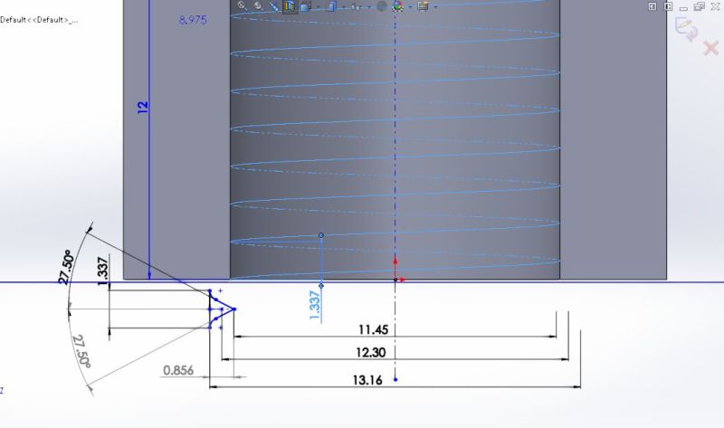
I would like to model a stand size BSPP 1/4" type part with internal and external threads that will work with standard 1/4" threads.


I can't seem to find a way to cut the profile and feeling a little lost on the point where I pierce on to the helix.
Could anyone help please?
Thanks.

My Solidworks 2014 3D CAD file is downloadable here -
 
Replies continue below

Recommended for you

Hi Dan,
Thanks for the information at the FAQ.

Hi Madmango,
I've seen that video before. Question is I'm not sure what is the thread size being used and I can't relate.

Based on the 1/4" BSP type I require, I'm stuck at where to pierce the profile. OR maybe I'm doing it wrong or is my profile incorrect?
My hole diameter for internal thread is 11.7 and the cylinder diameter for the external thread is 13.0mm
Hope someone can take a look at it.

Section_View_of_1-4_BSP_b1wxaa.jpg


Thanks a lot.
 
It's a good exercise, and I'm sure you'll eventually get it right,
but 3D printing to make the actual part will take longer
than machining it from billet.


Mike Halloran
Pembroke Pines, FL, USA
 
@ Mike : becos i'm Stuck ... that's why I'm here. Just want to find out how to model it on CAD b4 Printing.
I understand it's probably better to tape the threads (external/internal) after printing too.
But I kinda need to get the right dimensions at least right?
Anyway ...
 
I'd be inclined to model the part as a blank, suitable for machining, model the two helices as separate parts, and subtract them from the blank.

For printing, I'd make the hex a size or two bigger than is customary for metal fittings, and make the bore inside the male thread a couple mm smaller than is customary for metal fittings, to compensate for the reduced strength of plastic relative to metal. I'd also include generous radii and fillets where you show sharp corners.

I would not attempt to cut threads on a 3d-printed blank, because I'd expect the tear-out of tapped or die-cut threads from internal printing imperfections to be even worse than the printed thread surface.

I was not suggesting 3D printing a blank, but just machining the whole thing from solid hex barstock of plastic or metal or whatever you like, because it's just a couple of hours' work in a lathe, and printing the part will surely take longer than that.


Mike Halloran
Pembroke Pines, FL, USA
 
@ Mike : Yeah ... i get what you mean :D seems easier to machine out.

But for obsessive purposes, do you think you can take a look at where my CAD is wrong? :D
 
I sure wish I could, but I don't have access to a Solidworks seat,
and none of my home computers are powerful enough to run it.


Mike Halloran
Pembroke Pines, FL, USA
 
blohsg,
It looks like your Sketch17 of the thread profile was inverted. Your diagram is missing the radius value, and I'm not familiar with British Pipe Threads. See attached model, you can probably teak it to the correct proportions from here.

"Art without engineering is dreaming; Engineering without art is calculating."

Have you read faq731-376 to make the best use of these Forums?
 
 http://files.engineering.com/getfile.aspx?folder=65f338e6-fdb7-4d64-9466-a50adc3d0f55&file=Pipe2.SLDPRT
Status
Not open for further replies.
Back
Top