Trying to model a surface/web with corner joggle on both sides. Best to illustrate it with a picture.
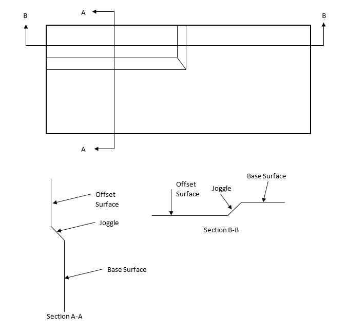
What I've omitted from the above drawing is the fillets that I want near the joggle i.e. in the sectional views, I want fillets on both sides of the joggles. Did not show it in the drawing because it is tedious to draw it in Word. The offset distance I am thinking right now is around the value of the plate thickness (0.080in).
So far, I've been able to create a surface stamp with parameters as shown below
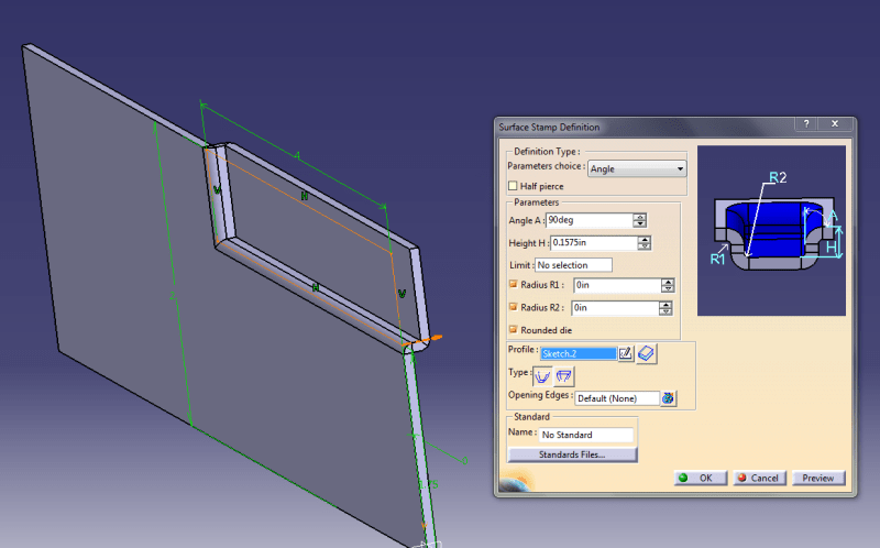
The fillets on the inside (R1, R2) is missing and also if I reduce the height to equal to sheet metal thickness (0.080in), Catia V5 gives me an error. If I try to include even a small radius value other than zero, Catia gives me an error of not being able to compute the fillets between the stamp & its support.
Just to give additional info, I made a closed rectangular sketch of the outlines where I want the stamps/joggles & used Surface Stamp command.
Hoping to get some tips on how to model the above.
What I've omitted from the above drawing is the fillets that I want near the joggle i.e. in the sectional views, I want fillets on both sides of the joggles. Did not show it in the drawing because it is tedious to draw it in Word. The offset distance I am thinking right now is around the value of the plate thickness (0.080in).
So far, I've been able to create a surface stamp with parameters as shown below
The fillets on the inside (R1, R2) is missing and also if I reduce the height to equal to sheet metal thickness (0.080in), Catia V5 gives me an error. If I try to include even a small radius value other than zero, Catia gives me an error of not being able to compute the fillets between the stamp & its support.
Just to give additional info, I made a closed rectangular sketch of the outlines where I want the stamps/joggles & used Surface Stamp command.
Hoping to get some tips on how to model the above.