Continue to Site

Eng-Tips is the largest engineering community on the Internet

Intelligent Work Forums for Engineering Professionals

  • Congratulations IDS on being selected by the Eng-Tips community for having the most helpful posts in the forums last week. Way to Go!

How to obtain the Moment-Curvature curve for the given steel connection.

Status
Not open for further replies.

M MOTAAL

Structural
Aug 22, 2018
22
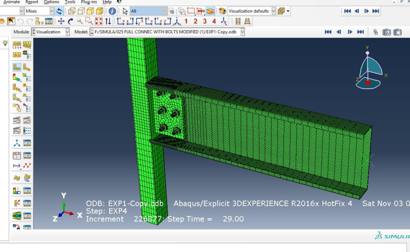
Hi everybody. I have the created and submitted the model in the figure attached below. I need to know how I can extract the moment curvature of the connection just to get rotational stiffness during different stages of loading and steps. I have surfed the net to find a solution but all what I got is how to get the moment using section cut. Is maintaining the rotation needs some like procedure? and if it's right to get the moment from free body section cut where should I take my section is is it to be along the whole connection or only through a specific object such as the beam for example and how to get the rotation?. Any help is greatly appreciated and thank you in advance.
001Capture_w5kkre.jpg
 
Replies continue below

Recommended for you

Typically like you might already know and done, one can create a RP (like you have done I can see), then apply a RBE-like coupling (e.g., distr. or kinematic.) at that point and at the free edge of the c-section and apply the moment there (RP). Use then perhaps arc length (Riks) to solve, since you are looking at capacity and beyond.

On the coupling link and at that RP, in the post processor. measure/get the applied moment and the rotation there. Plot those against each other and one can see the capacity from that graph. It will be the point in this load displacement curve where it goes more or less flat.

Load displacement curves have been previously discussed here so look and search for that in this forum and on the internet. (one link is:
Cheers
 
Hi Erik Panos Kostson I want first to thank you for fast response and secondly to point out some points in the model so as it may help understand my question for further benefit from your experience for me at least.
I have three more questions:
a) Now you have kindly shown me a new method (I mean new to me) to relate a surface to a RP. I used to represent using ordinary rigid body tie and here I want to ask if it really differs or you advised me to use Kinematic Coupling just for the sake of measuring different quantities at the RP.
b) I am using displacement control method in my model by applying constant displacement rate at the RP equals to
2.50 mm/minute in global y direction, which means the problem a quasi static one. My objective is to maintain the rotational stiffness through moment-curvature plot during the loading process up to failure. So I am not applying moment at the free end of the C-channel. I am really confused about where and how should I measure the moment and the curvature.
c) As I mentioned loading rate is very low and the problem is classified as quasi static.I am using ABAQUS Explicit to solve it. But you noted me that Riks is a convenient method to solve such a situation. Could you make further explanation why did you suggest Riks from the first while?
Best Regards.
 
No worries, but looking closer at your question you refer to obtaining the rotational stiffness of the connection (moment vs rotation), something I have never done, and do not know how to do exactly. (As for obtaining the total moment somewhere on the cross section, like you say, one can make a free body cut and get the resultant forces and moments)

Normally when I teach, say a connection example, the aim is to obtain the capacity (not the stiffness). So looking at the applied force vs deflections, or moment vs rotation at the point where we apply the force or moment.

For SHS or a CHS, the point of load application is many times on the centreline of the section, thus there is no node there. In Strand7, which is the software I use, one can use a rigid link cluster/spider, or a multi-point link cluster, to obtain a node on the centre line where we can apply the load onto. Very often these two are what is called RBE constraints (Nastran name), and are more specifically RBE2 and RBE3 respectively in Nastran (often used like explained here for remote load application). These two translate as kinematic (RBE2/rigid link) and distributed (RBE3/multi-point) coupling in Abaqus. For more information see the manual.

Finally last time I used explicit time integration (used to solve dynamic equations), was over 10 years ago and for research purposes so I do not have much practical experience. Of course I remember that the stable time increment since it is a conditional stable scheme can be very small (~1E-7s to ~ 1E-5 s, assuimg 1 to 100 mm typical elements size), due to the high speed of the fastest wave in steel (~5000 m/s for the longitudinal wave in steel) thus many time steps are needed to resolve long quasi static runs, even perhaps with mass scaling which I never used.

Now what you want to use in terms of solver it is up to you not me so just choose what you want. For me though since there is not an explicit solver in Strand7 (an implicit exists, and is used in Strand7 say for nonlinear structural dynamics, not for static problems), when I do say the connection example mentioned above (static problem), I will use of course the nonlinear static solver (including all nonlinearities), which uses standard NR iterations to solve a static NL problem (thus no inertia and mass matrix, so only K*u=F is solved). Since convergence can be difficult when this structure collapses and softens the arc length (called Riks in abaqus) sub stepping scheme is used to aid convergence, helping to obtain a solution in Strand7 (in the implicit schemes arc length does not exist, hence the sensible choice of using a nonlinear static solver to solve a static problem with the aid of arc length).
 
Thank you Erik for your time and explanation. I am replying late because a harmful virus had infected my device and I had to spend some time restoring my backups from everywhere. Now I managed to solve the model by means of using Implicit Dynamic step and the convergence is running perfectly with a very fast rate up to the 300th second of natural time of the quasi static problem. But when the model reach some stage during which large plastic deformations take place the convergence rate begins to be very slow. It is still running but at much slower rate which is a single digit times 1e-5. Is there anyway to increase the rate of conversion? I tried to change the "Time Incrementation" settings and ticked the "Discontinuous Analysis" option to activate it, but didn't fix the issue. Do have any idea how to quicken the convergence during plastic deformations taking place? I need to run the model up to tearing out of the connection.
By the way I used to simulate my models with the same natural time of the physical problem as the time period of the steps of solution. Do you think this may cause me troubles?
 
That is the drawback of the implicit method (needs NL iteration for every time step). Thus for sever nonlinearities it can take many iterations to get convergence (due to nonlinear things going on), so it might need to reduce time and cut back (forces and and displacements) if convergence is not obtained, so it can take time. Perhaps then explicit is not too bad after all :). It is perhaps a trade off between the smallest step to total time (in explicit), and the amount of cut back/substeps needed in implicit (in order to obtain convergence). I would just let it run over the weekend.
 
Status
Not open for further replies.

Part and Inventory Search

Sponsor