Eng-Tips is the largest engineering community on the Internet

Intelligent Work Forums for Engineering Professionals

  • Congratulations waross on being selected by the Tek-Tips community for having the most helpful posts in the forums last week. Way to Go!

How to Pattern Assembly holes in Catia V5 1

Status
Not open for further replies.

aleseg

Mechanical
Jul 30, 2020
37
0
0
IT
Hi

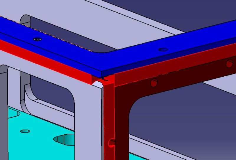
I'm building a chassis that need to be welded in its parts, I have had to use the Assembly holes feature to make an hole that go through different parts and I manage to do it; the only problem that I have is find a way to pattern this assembly hole ( I need to repeat it X times ) because I can't find any command to do it.
Any suggestion?
 
Replies continue below

Recommended for you

Hi

Thanks for the reply, could you please show me the command? I have tried with the Ctrl+D or Ctrl+E but it doesn't recognize the assembly hole function.
 
You are not able to pattern the assembly features/holes (at least not with my R26 license bundle)

Since the assembly feature dumps the hole feature into each component file anyway, I would suggest creating the holes in each component. In R25 and above, you can use User Pattern and select axis systems/points/sketches/other to position each location in whichever direction/location you choose. In versions prior to R25, your choices are limited for position references.

 
Hi

Thanks for the reply. I suspected that I cannot patter assembly holes, a little disappointed by the way. I'm using CATIA V5-6 R29 but it's the same as your versione apparently.
The problem is that I have to make this hole series that cut 3 different components actually is kind of rare situation.
Doing the hole in each components it means doing the "incomplete hole" in eaach component, maybe I can do the assembly hole every time...I'll see that.

By the way I have another problem, I'm using the welding design feature, I have this situation:

Annotazione_2020-07-31_085520_nbg7bp.jpg


where 3 different weld seams should reunite in 1 vertex, is that possible to create a continum seams instead of the 3 different seams that leave the empty volume zone?

Thanks.
 
Hi,
I cannot help with your welding issue but as far as creating matching holes in different parts of an assembly, here is what I will usually do.

1. In one of the parts, I create a sketch with points. The points would represent hole centers. Create a hole. Use user defined pattern & sketch to create copies of the hole. The sketch plane preferably should be in a plane common to mating parts.

2. Publish the sketch

3. Copy the published sketch in to mating components catparts (past -> Result with link option)

4. Create hole & pattern the same (user defined) as done in previous part.

The beauty with using published sketches is that if the original sketch is modified, the changes are reflected to all parts/components using the published item and auto updated.

Google up on how to publish an item & its usage.

I wish there was a feature where one can directly create holes during assembly process in Catia, but the above procedure generally work well although it involves additional steps.

I will ask a question of my own here. While creating fastener pattern sketch, I usually translate points. Is there a way to create automatic dimensional constraints between these points in Catia V5 sketcher mode. I want the spacing between these points to be per certain industry standards, which means that modification should be easy. Currently, I am finding it easier to recopy them points.
 
Hi VN1981, you can use Equidistant Points Definition and in sketch tool toolbar - geometric and dimensional constraints option must be activated .

Best regards
 
Status
Not open for further replies.
Back
Top