Eng-Tips is the largest engineering community on the Internet

Intelligent Work Forums for Engineering Professionals

How to set CSYS (absolute coordinate system)

Status
Not open for further replies.

wedxza

Mechanical
Jun 25, 2015
20
0
0
US
1111111_w7mjx4.png
2222222_wubutr.png

333333_yvbrsa.png


Hi everyone,

I have question about setting up the CSYS.

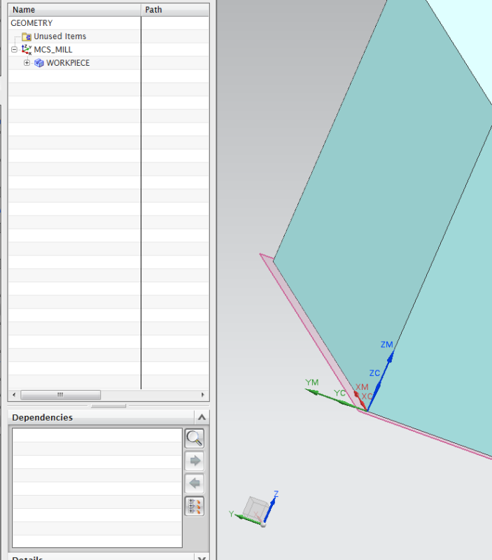
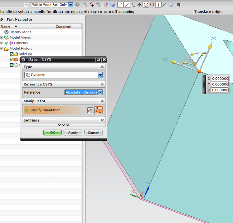
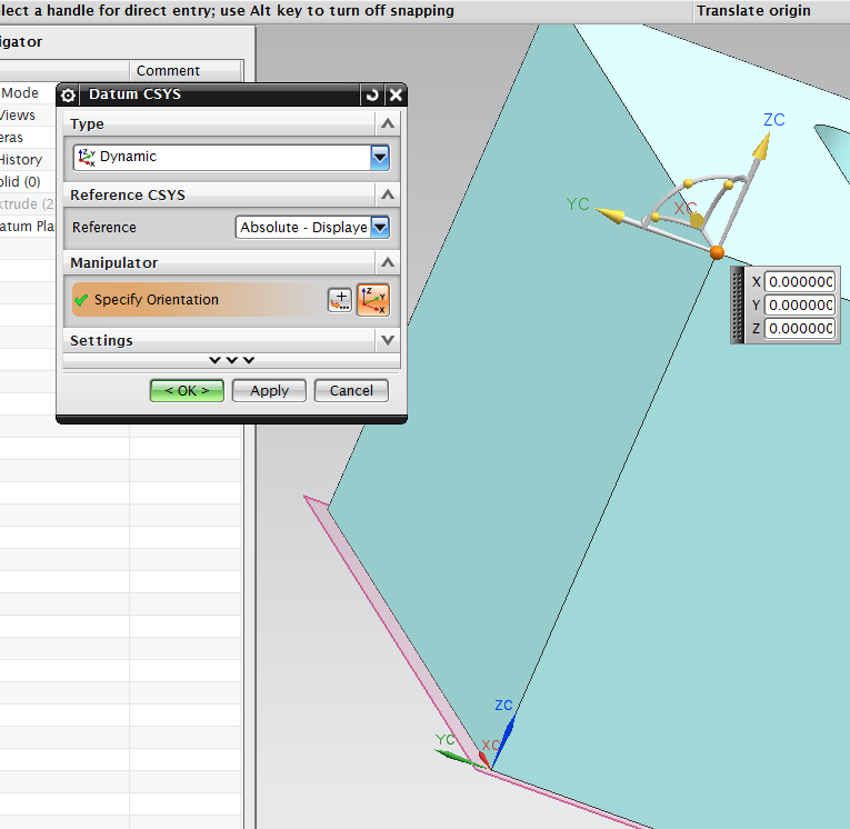
The origin of the absolute coordinate system is on top. I wish to set it on the bottom, same spot as WCS, MCS...
Although I set WCS, MCS and reference to the bottom of the part. But it seems that all these three coordinate system are taking the CSYS(absolute coordinate system) as the reference.

Can anyone help?

Attached are the screen shots, 111111 & 22222

Thanks
 
Replies continue below

Recommended for you

You cannot move the absolute CSYS of a model. That's why they call it 'Absolute'. Now if you absolutely (excuse the pun) need to have the 'absolute' CSYS somewhere else on your model, you will need to to Move the model.

Now this can be done either in the detail part itself, or you could create a Master Model assembly where you add the part as a Component at whatever location and orientation that you wish and then simply use this part file for whatever you intended (sounds like you're planning some manufacturing operations, like tool path generation).

John R. Baker, P.E.
Product 'Evangelist'
Product Engineering Software
Siemens PLM Software Inc.
Digital Factory
Cypress, CA
Siemens PLM:
UG/NX Museum:

To an Engineer, the glass is twice as big as it needs to be.
 
You cannot move the absolute coordinate system.

"Know the rules well, so you can break them effectively."
-Dalai Lama XIV
 
I am curious - Why are you concerned with the absolute CSYS?
It is mainly a permanent reference.
In CAM you use WCS for input, and MCS for output, and i fyou want to input in MCS coordinates, you can set a preference for the WCS to always align with the active MCS.

Mark Rief
NX CAM Customer Success
Siemens PLM Software
 
I tried to output the NC code. No matter how I set the WCS and MCS, it always take the absolute coordinate.


When I define the origin of WCS on the bottom. In manufacturing simulation, I need to add the height of the block to the "translation in Z axis" . Otherwise, the machine will mill through the whole part.
When I define the origin of WCS on the top, I don't need to make any change in the simulation, it seems that it is because the origin of the absolute coordinate system is the same as the WCS. Machine will just mill the designated pocket on the top.

There is probably something wrong with the code output of the APT format that I chose. It only calculated according to absolute coordinate, ignored the WCS ect. Or I might set the parameters wrong. Still need to find out more.

Thanks
 
Your output should not be in absolute, unless you have written a very customized postprocessor.

If you are new to NX CAM, the geometry view of the Operation Navigator determines which MCS each operation uses. So be sure that your operation is under an MCS group, and that MCS is where you want it.

An easy check is to list the tool path, which uses the MCS coordinates.

Mark Rief
NX CAM Customer Success
Siemens PLM Software
 
I just tried the Mori APT output on a simple hole and the coordinates are MCS.

Code:
Listing and CLSF output:
CYCLE/DRILL,RAPTO,2.5000,FEDTO,-50.0000,RTRCTO,AUTO,MMPM,250.0000
GOTO/-16.9082,-58.6182,0.0000

Mori APT Output:
CYCLE/DRILL,CLEAR,2.5000,DEPTH,50.0000,RETURN,0.0000,PERMIN,250.0000
GOTO/-16.9082,-58.6182,-50.0000,0.0000000,0.0000000,1.0000000

If you are not getting MCS, please contact GTAC so that they can investigate and log a problem report if needed.

Mark Rief
NX CAM Customer Success
Siemens PLM Software
 
wedxza said:
Which NX version did you use?

I used NX 10.0.2. It's possible the problem you see has been fixed - this is why you should contact GTAC. They can try your test case in the latest version.

Mark Rief
NX CAM Customer Success
Siemens PLM Software
 
Status
Not open for further replies.
Back
Top