enghelp2806
Aerospace
Hello,
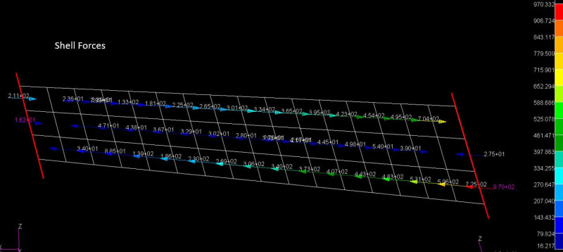
I'm trying to size this frame, which is essentially a beam fixed/pinned on either end and loaded externally. The FEM is basically a global model (other components not shown) used to distribute loads and isn't used for stresses due to its coarseness. What I have below is the frame, plotted with the shell forces of each element along the length of the part.
What would I do with these shell forces to size the part? This is just a preliminary sizing, nothing detailed or final just yet, which is why I want to go this route.
1. I could take the max force, but would that be the max force of any one element, or the max of the summed forces of 3 elements along the z axis?
2. I could take the average force, but would that be the average force of all elements, or the max of the average force of 3 elements along the z axis?
Thanks