Continue to Site

Eng-Tips is the largest engineering community on the Internet

Intelligent Work Forums for Engineering Professionals

  • Congratulations KootK on being selected by the Eng-Tips community for having the most helpful posts in the forums last week. Way to Go!

How to specify drag/collector load to truss supplier?

Status
Not open for further replies.

MJC6125

Structural
Apr 9, 2017
120
I have some questions on how people typically specify drag/collector loads to truss suppliers.

See diagram below as a simple example. I understand what the loads are doing in the diaphragm and in the shear wall. But I'm a little confused on what they do through the pre-engineered trusses.

1. For this example, would you specify loads on your plans in a "kip" or "klf" format? What value would you give (i.e. design all three drag trusses for 10 kips, design all for 4.2 kips, design end trusses for 3.3 kips and middle truss for 4.2 kips, or design all trusses for 0.167 klf unit shear)?
2. How exactly does the truss designer apply this force to their truss design? Added axial force to the top chord that they apply at the end of the truss? Unit shear that gets applied all along the top chord?
3. How does the truss designer resolve the force? For the middle truss, it would leave the truss through the bottom chord. If I locate the strap connecting the end and middle trusses at the top chord, the force would have to transfer out through that top chord of the end trusses. Is this something that goes into their truss design? Would it make a difference in their design?
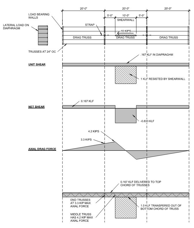
Drag_Truss_druq0p.jpg
 
Replies continue below

Recommended for you

your central truss sees the full 10k. if it's the one delivering the load to the shearwall it sees it all no matter what. The two outer trusses would see lesser amounts.
 
1) This can make a substantial difference in the design of some trusses, particularly with respect to the demand for bottom chord bracing and tie downs.

2) This is much easier for the chord function than it is for the drag function. With chords, you usually just see the reversible arrow symbol and values specified in kips.

3) For the drag function on that center truss, I feel that your only real hope is to draw atruss profile with your anticipated, laterally originated forces on them. Otherwise, there are just too many non-obvious interpretations that the truss designer might make trying to capture your intent. Heck, you and I probably couldn't nail it 100% without some sketches.

4) I like this done in tabular fashion where you'd draw a profile of a truss with some loads on it and a shear wall below that is only present if present in plan. Then your table columns would be something like [MARK; BC LEFT AXIAL (lbf); BC RIGHT AXIAL (lbf); TC AXIAL (plf); TIE LEFT (lbf); TIE RIGHT (lbf); SW LENGTH (ft); SW AXIAL (plf)]. It sounds like a lot of effort but:

a) It's all stuff that you can dump out of a spreadsheet and hand off to drafting.

b) It forces the EOR to think through things properly.

c) For the delegated engineers, it's much easier to work with a complete story that is comprehensible rather than a bunch of conservative numbers that tell no story at all. As one who has designed both pre-engineered trusses and precast, I can tell you that 2/3 of the EOR plans that I see are pretty much unintellible when it comes to lateral, partly for this reason. What those EOR's will get from me is conservative solutions for their clients and, often, a story told by me that probably does not match the story told by them.
 
5) Truss design software is pretty fancy these days. You can pretty much specify any load and the designers will be able to input that into their software or, at worst, approximate it somehow. The issue is really adequate communication of what you want as the EOR, not whether or not they can process the design of it.

6) I find it simpler to assume that all of my truss end chord axial forces are transferred through the bottom chord, especially for pitched trusses. Obviously, this is something over which it is difficult to exert perfect control. But, then, we can't let the perfect be the enemy of the good.
 
[ul]
[li]I just post the maximum load in kips, plus a fudge factor. Your other representations, while more technically accurate, will likely confuse the truss designers. They're (the truss designers) very much into having the EOR make all the decisions and just provide a truss that meets them. Interpretations are not included.[/li]
[li]I believe the truss designers apply the load to the top chord and add lateral bracing or bridging if necessary.[/li]
[li]Not sure of the specifics, I assume they let you worry about the ends or transfer.[/li]
[/ul]
 
I appreciate the responses.

KootK said:
4) I like this done in tabular fashion where you'd draw a profile of a truss with some loads on it and a shear wall below that is only present if present in plan. Then your table columns would be something like [MARK; BC LEFT AXIAL (lbf); BC RIGHT AXIAL (lbf); TC AXIAL (plf); TIE LEFT (lbf); TIE RIGHT (lbf); SW LENGTH (ft); SW AXIAL (plf)].

So what would your values be for the middle truss in this example?
BC LEFT AXIAL = ?
BC RIGHT AXIAL = ?
TC AXIAL = 167 plf?
TIE LEFT = ?
TIE RIGHT = ?
SW LENGTH = 10 ft
SW AXIAL = 1000 plf

If you chose to splice either the top or the bottom chord of your trusses together for the drag force (strap on top or strap on bottom), would it change what you put in that table above?
 
BC LEFT AXIAL = 3.3 kip
BC RIGHT AXIAL = 3.3 kip
TC AXIAL = 167 plf
TIE LEFT = 1000 plf x Truss Height
TIE RIGHT = 1000 plf x Truss Height
SW LENGTH = 10 ft
SW AXIAL = 1000 plf

You might have some negatives in there depending on how you choose to show things in your generic diagram.

OP said:
If you chose to splice either the top or the bottom chord of your trusses together for the drag force (strap on top or strap on bottom), would it change what you put in that table above?

Yes, it would change things. Some reasons that I like the bottom chord ties:

1) Simplicity in the presentation that we've been discussing. Not concentrated loads having to move from the bottom chord to the top chord.

2) At the shear wall, the wall forces send load directly into the bottom chord so there's not getting around it there.

3) It shares the OT tie forces among all of the trusses rather than just concentrating them at the truss over the shear wall. At least, that's the story I tell.

4) It's a pedantic point but I don't like the top chord tension ties making continuous trusses out trusses designed to simple span, even if the ties go on after some of the dead load.

I realize that folks like to say that all of the load in the top chords because those chords come with natural bracing.
 
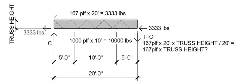
For the tie left and right forces would those be equal to the diaphragm shear x truss height instead of shear wall shear x truss height. Below is the FBD that I'm seeing. Maybe I'm missing something?

Drag_Truss_2_htysxr.jpg
 
Yup, that's precisely the mddel that I had in my head as we were discussing this.
 
Status
Not open for further replies.

Part and Inventory Search

Sponsor