Navigation
Install the app
How to install the app on iOS
Follow along with the video below to see how to install our site as a web app on your home screen.
Note: This feature may not be available in some browsers.
More options
Style variation
-
Congratulations TugboatEng on being selected by the Eng-Tips community for having the most helpful posts in the forums last week. Way to Go!
You are using an out of date browser. It may not display this or other websites correctly.
You should upgrade or use an alternative browser.
You should upgrade or use an alternative browser.
How to study this structure 1
- Thread starter gtsolid
- Start date
- Status
- Not open for further replies.
- Thread starter
- #3
gtsolid,
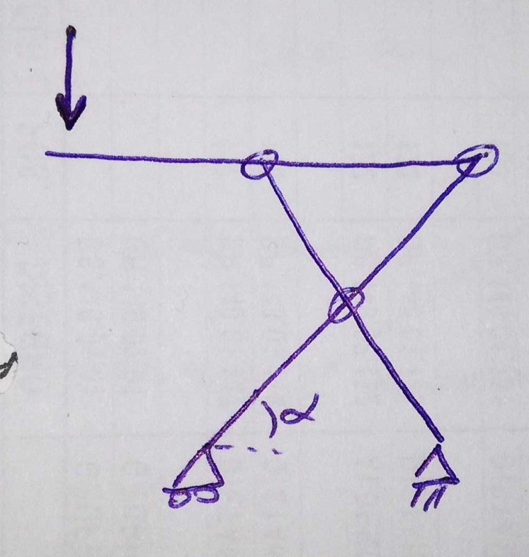
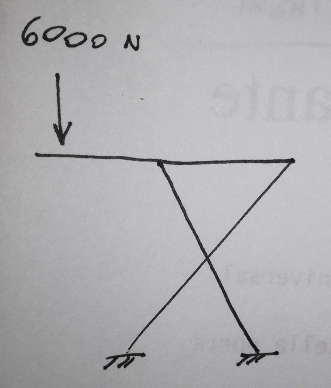
You show both reactions on the bottom as fixed. This makes your structure statically indeterminate. Are your beams connected at the "X"? You need to account for bending of your structure. This is not straight tension and compression.
--
JHG
You show both reactions on the bottom as fixed. This makes your structure statically indeterminate. Are your beams connected at the "X"? You need to account for bending of your structure. This is not straight tension and compression.
--
JHG
look at the top 1/2 of the structure; make a FBD of it. This should tell you that the two inclined members are in bending; not the end of the world, and not inconsistent with a pin joint between them (where they cross).
The structure is, as noted above, indeterminate with the two fixed supports. Two pinned joints are also indeterminate (although this greatly simplifies the structure to a "simple" three force member, but there are still an infinite set of solutions. One pinned and one roller joint is determinate (now simply a beam with an overhang point load).
now, of course, there are simple solutions (ie treat the problem as an overhanging beam) but this doesn't match the problem as shown. In the simple solution, the moment at the joint is reacted as a couple at the two reaction points. Adding reaction moments changes the couple; adding equal and opposite lateral reactions (allowed by the supports as shown) also compounds the solution (or confounds the solver).
another day in paradise, or is paradise one day closer ?
- Thread starter
- #9
this is a scissor lift, yes. The point is that at university we never studied this kind of structure. only single beam.
in the upper part i think this is a better scheme:

There is a ball screw who governs the extension in the lower support at left.
in the upper part i think this is a better scheme:

There is a ball screw who governs the extension in the lower support at left.
gtsolid, In your original post you asked for help with the reactions in the upper member. Then you said that you have only studied reactions in single beams. I think your professor is teaching you a very valuable lesson - how to see applications for what you know in the real world. He confused you by adding a lot of extra information you don't need. (They love to do that to teach you to look for what you need to know and ignore the rest.) The upper member is a single beam, supported at two points and loaded at a third. The rest of the picture makes no difference. If the upper beam and all its support points and its load are all defined, you've got all you need.
- Thread starter
- #11
I have 18 dof, this because i have 3 beams, each with 6dof.
Every simple joint removes 2 dof (2n-1 where n is the number of beam linked by the joint).
In the bottom parte i have a pin support in the right, removing 2 dof, and a roller in the left side, so another dof is going away. How can i remove the others?
i would to find the force i have to apply in the roller to keep the structure stopped
ok, sounds less like school work, and the sketch is better.
first, there are lots of threads on scissor lifts, try reading them to get ideas.
second, review free body diagrams, then see how to apply them to the problem. some clues ...
1) break the problem into three pieces, the three different members; as well as looking at the structure completely as a free body (ie what ground reactions will react the applied load).
2) consider the top beam. one (the RH one) joint is almost certainly hard located (fixed in position, at the end of the beam) but the LH will slide along the beam. this is not quite as you've shown. this has implications for the reactions on the LH support.
3) the top beam will solve without moments at the supports. It is hard to see how a practical structure would have moments (I'd expect to see pins at these locations).
4) then consider each arm as a free body. Start with the one with the actuator load applied. You have to determine the load at the middle joint, that passes from one inclined member to the other. I think you know the other loads on this member.
third, an important detail ... you mention the actuator, Does it attach to the opposite leg or to the ground ? If the ground, the problem just became indeterminate again (maybe) ! Though you may be able to figure the actuator load from the work done.
another day in paradise, or is paradise one day closer ?
- Thread starter
- #14
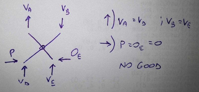
where is the actuator load ? without the actuator you don't have a structure. what's holding the inclined members at their angle ? you can build a model of this and see for yourself.
Why is the solution "no good" ? Does this mean the two members as individuals don't balance ? because you haven't included the load transferred between them at the pivot. and because you don't have the actuator force keeping the inclined members in position.
Your solution assumes that the inclined members pivot about their mid-point, which may be correct but doesn't have to be.
another day in paradise, or is paradise one day closer ?
msquared48
Structural
In your top diagram, the top pin to the left will have to be a horizontal slide/roller connection to allow the "X" to translate laterally at the top.
Otherwise the scissor effect will not work.
Also, "P" will have to have a non-zero value, otherwise no lifting will occur.
Mike McCann, PE, SE (WA)
Otherwise the scissor effect will not work.
Also, "P" will have to have a non-zero value, otherwise no lifting will occur.
Mike McCann, PE, SE (WA)
Compositepro
Chemical
This thread is an example of why student posting is not allowed on eng-tips.
- Thread starter
- #18
-
1
- #19
Please see:
Solving this problem involves several principles from this course.
-handleman, CSWP (The new, easy test)
Solving this problem involves several principles from this course.
-handleman, CSWP (The new, easy test)
gtsolid,
Go back and visualize your structure, then draw a free body diagram. As rb1957 notes, your actuator is part of your structure. Include it in your diagram. If the forces on your two "X" beams are not directly in line with the beams, then you have to analyze for bending. This should not (significantly) affect the forces from your statics analysis.
--
JHG
- Status
- Not open for further replies.
Similar threads
- Replies
- 2
- Views
- 3K
- Question
- Replies
- 1
- Views
- 2K
- Question
- Replies
- 9
- Views
- 861
- Question
- Replies
- 23
- Views
- 5K
- Replies
- 20
- Views
- 10K


