Navigation
Install the app
How to install the app on iOS
Follow along with the video below to see how to install our site as a web app on your home screen.
Note: This feature may not be available in some browsers.
More options
Style variation
-
Congratulations TugboatEng on being selected by the Eng-Tips community for having the most helpful posts in the forums last week. Way to Go!
You are using an out of date browser. It may not display this or other websites correctly.
You should upgrade or use an alternative browser.
You should upgrade or use an alternative browser.
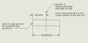
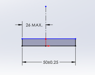
How to use profile of surface feature control frame to control max. protrusion?
- Thread starter jassco
- Start date
- Status
- Not open for further replies.
- Thread starter
- #3
So, make the profile of surface tolerance [1000 (U) 0] or any other value that is large enough.
Feature Control Frames (not GD&T) and geometric characteristic symbols define the range of variation from some nominal condition (not always a fixed boundary, e.g. circularity) and "MAX" isn't a range. Unlike diameter, there isn't even the possibility in this case of noting that 0.00 is the natural barrier to some "MAX" diameter for a hole or a pin.
Feature Control Frames (not GD&T) and geometric characteristic symbols define the range of variation from some nominal condition (not always a fixed boundary, e.g. circularity) and "MAX" isn't a range. Unlike diameter, there isn't even the possibility in this case of noting that 0.00 is the natural barrier to some "MAX" diameter for a hole or a pin.
CheckerHater
Mechanical
With MAX dimension the other limit is ZERO, not INFINITY.
So the unilateral tolerance cannot be larger than 26.
Question: should it really be MAX?
So the unilateral tolerance cannot be larger than 26.
Question: should it really be MAX?
- Thread starter
- #9
mfgenggear
Aerospace
OP
That is why I said you can't.
There is a missing detail or datum where the centerline is derived from. The drawing is incomplete.
The centerline is not drawn on center.
And is projected from where?
That is why I said you can't.
There is a missing detail or datum where the centerline is derived from. The drawing is incomplete.
The centerline is not drawn on center.
And is projected from where?
- Thread starter
- #12
- Thread starter
- #14
mfgenggear
Aerospace
Op
What many machinist freak out is when is a max. They try to make as close as possible to max dim. I have struggled with that as well.
Truth any dim. Under the 26 max stands on its own. And is acceptable. No other tolerances required.
A clarification note would be helpfull to alieve questions.
What many machinist freak out is when is a max. They try to make as close as possible to max dim. I have struggled with that as well.
Truth any dim. Under the 26 max stands on its own. And is acceptable. No other tolerances required.
A clarification note would be helpfull to alieve questions.
- Status
- Not open for further replies.
Similar threads
- Question
- Replies
- 8
- Views
- 13K
- Question
- Replies
- 3
- Views
- 2K
- Locked
- Question
- Replies
- 7
- Views
- 1K
- Locked
- Question
- Replies
- 14
- Views
- 1K
- Locked
- Question
- Replies
- 9
- Views
- 5K


