Eng-Tips is the largest engineering community on the Internet

Intelligent Work Forums for Engineering Professionals

how to write a parameter in APDL code inside workbench file ? 1

Status
Not open for further replies.

md_salem

Civil/Environmental
Jun 18, 2023
13
0
0
EG
Hello every one,
I had to write some APDL code inside harmonic analysis in workbench file.
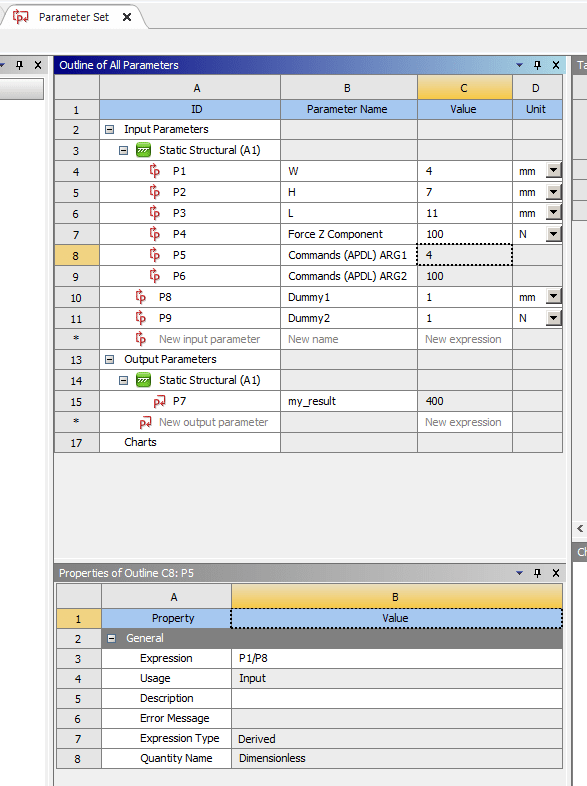
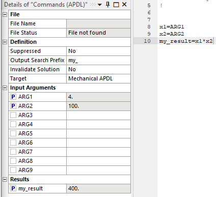
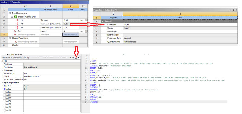
Inside this APDL code, I applied some force to the system (f) where the value of (f) is determined from relation (f= S*A*b) where S and A are constant while (b) is parametrized in order to carry out optimization. how to deal with parameterized (b)in the APDL code given that it is dimension.
Regards
 
Replies continue below

Recommended for you

Hi,
just put a Commands (APDL) under Analysis Settings. Tick Input Arguments in Details of "Commands (APDL)", this allows you to do parametric study. Put a code into it

Code:
S=2                      !Constant
A=3                      !Constant
b=ARG1                   !Input argument ARG1
f=S*A*b                  !Force

cmsel,s,force            !Select face from named selection named force
nsle,r                   !Select all nodes belong to the face, or you 
                         !can create a named selection with nodes and
                         !skip this nsle,r commnand

*get,ncount,node,,count  !Get number of selected nodes
*get,nnum,node,0,num,min !Get lowest index of node

fnode=f/ncount           !Force has to be divided into nodes

*do,i,1,ncount,1         !Loop over all selected nodes
 f,nnum,fy,fnode         !Apply force of magnitude fnode, in direction Y
 nnum=ndnext(nnum)       !Next node in the list
*enddo

allsel

Best regards
Jiri
 
Note that this only works for linear 1st order elements. otherwise you will apply inconsistent nodal loads using this approach.
 
Hi there,
petb said:
you are right

To fix this, you may apply Coupling constraint or rewrite APDL code

Code:
S=2                       !Constant
A=3                       !Constant
b=ARG1                    !Input argument ARG1
f=S*A*b                   !Force

cmsel,s,force,node        !Select all nodes belong to named selection named force

*get,ncount,node,,count   !Get number of selected nodes
*get,nnum,node,0,num,min  !Get lowest index of node

narea=0                   !Reset variable node area
*do,i,1,ncount,1          !Loop over all selected nodes
 narea=narea+arnode(nnum) !Area at node nnum apportioned from selected elements attached to node nnum
 nnum=ndnext(nnum)        !Next node in the list
*enddo                    !End loop

pressure=-f/narea         !Calculate pressure, p=F/A
sf,all,pres,pressure      !Apply surface loads on nodes 

allsel

Best regards
Jiri
 
I am so appreciated for your sincere help,
I think some misunderstanding happened.
in the workbench file , while I was preparing my problem, I checked the parameter (b) to be parametrized (i.e the mark [P] appeared in the box next to (b) value in Workbench) .
I just want to know how to mention this parameter in my APDL code and how to get some variable from APDL code to be parameter!!
Regards
 
Hi jkupka84,
Appreciated for your concern,
let me explain the problem in details as simple as I can,
I am doing maximization problem, the objective is maximize energy done by some plate due to applied force at certain frequency. the parameters are the thickness and the force . (I can parametrize both thickness and applied force in the workbench from the beginning)
I did all the model on workbench
then I added the an APDL code to define the harmonic analysis and extract potential energy as a parameter (in order to use it as objective in the optimization process which is also done using workbench tools)
there is a relation between thickness and force ( some constant let's name it E = force/thickness)
the problem for me can be figured in next points :
* when I am writing the APDL code , how I can use the force and thickness in the upper formula ? I mean what codes or symbols does the workbench give them when I parametrize them ? so I can use them in the written APDL code ?

* if the E has to not exceed some value ... so when I define it in the written APDL code, how I can make it appear as a parameter in the workbench ? ( make it in the code = ARG1 for example or what ?)
best of regards


Hi md_salem,
due the dimensionless of APDL parameters, you have to create dummy parameters with a unit value of the dimensions (mm, N, Pa, etc.). To pass the parameters to APDL you have to write Expression in Parameter Set, see the picture.

2023-08-22_075117_isdecy.png


Best regards
Jiri
 
well,
that means when I need to deal with some parameter (that already defined in the WORKBENCH) in the APDL code I just put its "parameter name" like (W,H, L) in the APDL code. and when I need to create a parameter in the APDL to deal with it in the WORKBENCH I give it ARG1,2,3... ?
am I right ?
 
This is just an example. I created a simple model of a brick, defined as WxHxL (P1xP2xP3) in SpaceClaim to be sure how to handle different parameters into APDL code.

Inputs parameter of APDL code is ARG1, ARG2,...,ARG9. You may see it in Mechanical in the Details of "Commands (APDL)". In APDL commands you just write x1=ARG1, x2=ARG2, etc.

The output parameter(s) of APDL is given by Output Search Prefix in the same Details of "Command (APDL)", my_ by default. See the picture.

2023-08-22_123501_jomwd5.png


Best regards
Jiri
 
that is pretty good.
then, if I need to handle W or H or L in the written APDL, should I write them W , H, or L ? or P1, P2, P3 ?
Regards
 
If you want to use parameters from SpaceClaim, as I mentioned earlier, you have to change these parameters into dimensionless and then write in to the Expression field in the Parameters Set, please see my post above. These W, H, L are just parameters names, so it is readable for the user. Real reference name is P1, P2, etc. see the ID column.

Best regards
Jiri
 
Dear Jiri,
your code worked perfectly for the simple example that I have given to you.
I tried to develop harder situation
I am trying to apply deflection upon the surface of block with thickness 0.15 m , both deflection and thickness are variables (parameters). the thickness is defined with parametrization of extrude process in design modular with parameter ID P28 while the deflection is initially will be 0.1mm. I suppose to calculate potential energy. Here is a part of my code

/SOLU
u=ARG9 !I put 0.1mm next to ARG9 in the table then parametrized it (put P in the check box next to it)
ANTYPE,harmonic !harmonic analysis
HROPT,full
HROUT,on
LUMP,0
CMSEL,s,block,volu
NSEL,r,loc,z,0.15 !this is the thickness of the block which I need to parametrize, its ID is P28
D,all,uz,ARG9 !I put the value of ARG9 in the table 0.1 then parametrized it (put P in the check box next to it)
ALLSEL
EQSLV,,0
PSTRES,0
HARFRQ,X11,X21 ! predefined start and end of frequencies
NUBST,20
KBC,1
DMPRAT,8E-6
SOLVE
FINISH

when I ran this code it worked properly , I received a value for the potential energy and I have saw the ARG9 as a parameter in the optimization block. but when I replaced 0.15 (in the 8th line of code) with P28 the program returned 0 as a result for potential energy . I checked the "solution information", it showed that selected location of 'z' in the case of using P28 is set to be 0 despite the original value of the thickness is already set to 0.15m. what would you think is went wrong ?
best of regards
 
You have to pass your thickness parameter (P28 in your case) to input parameter of APDL code. I create an example, maybe it will be more clear for you. The parameter of thickness has a dimension, you have to change it into dimensionless parameter if you want to use it in APDL code. The deflection is pass directly into APDL.

example_yx7rzm.png


Best regards
Jiri
 
well, that is look pretty good.
in that case I think I have to parametrize both P1 and P4 (in your code)
take in consideration that P1 (thickness) is extrude length.
when I tried to identify the Dummy parameter it I couldn't put a unit (the unit cell is empty and I couldn't assign it to m _

Regards
 
Status
Not open for further replies.
Back
Top