Continue to Site

Eng-Tips is the largest engineering community on the Internet

Intelligent Work Forums for Engineering Professionals

  • Congratulations KootK on being selected by the Eng-Tips community for having the most helpful posts in the forums last week. Way to Go!

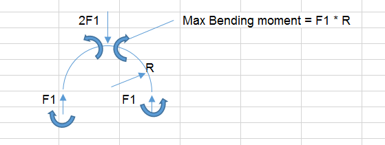
How would you analyze the local stresses in this arrangement (sketch attached 1

Status
Not open for further replies.
Replies continue below

Recommended for you

BS5500 PD5500 has charts and formulas for local loading on shells. These may cover your geometry.
 
Kevin, PD5500 Annex G looked very promising; however, my application does not meet the geometric restrictions for L, r, Cx, and Cphi.
 
Not a simple problem, that's why no simple treatment of it can be found in the literature. The closest similarity that I can propose is with saddle supports: here many papers exist (and also PD5500 has it), but generally the included angle is less than 180 deg and the saddle flexibility is far from being constant. This paper has a single case where the saddle angle is 180 deg.

prex
[URL unfurl="true"]http://www.xcalcs.com[/url] : Online engineering calculations
[URL unfurl="true"]http://www.megamag.it[/url] : Magnetic brakes and launchers for fun rides
[URL unfurl="true"]http://www.levitans.com[/url] : Air bearing pads
 
Kevin, Prex, thanks your time. This does appear to be a somewhat difficult case to analyze. I have been reviewing saddle support documents (Zick's and Roark's). I'll take a look at the paper you posted too, Prex.
 
Conservatively and easily you could consider the clamp as a point load on the shell and calculate the maximum bending moment in the shell. You could also consider a local bearing load stress at the point of contact of the point load on the shell.

max_B_wvfn2b.png
 
Status
Not open for further replies.

Part and Inventory Search

Sponsor