Continue to Site

Eng-Tips is the largest engineering community on the Internet

Intelligent Work Forums for Engineering Professionals

  • Congratulations KootK on being selected by the Eng-Tips community for having the most helpful posts in the forums last week. Way to Go!

How would you model this? And thoughts on lack of diagonal braces?

Status
Not open for further replies.

damorim

Structural
Jun 8, 2016
63
Hi everyone,

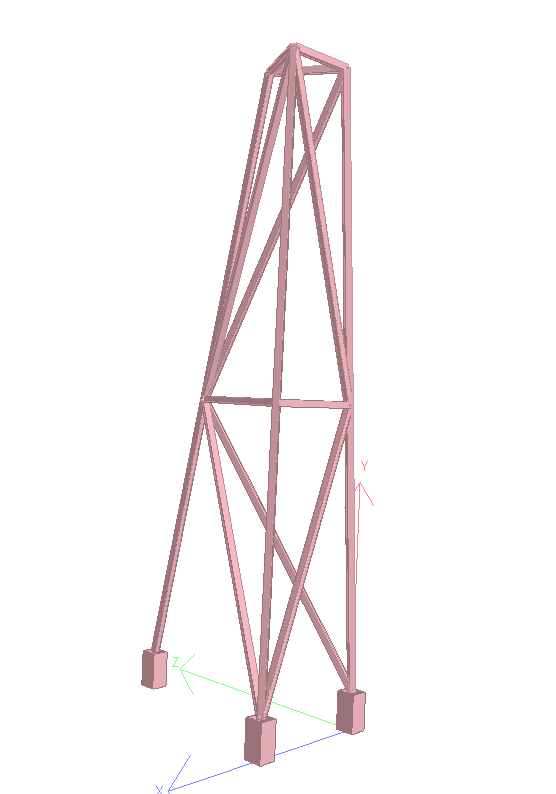
I just want to get your thoughts on how you would model this structure (having some differing opinions within office). Basically, the tank on top is being increased to hold more water and I am tasked with making sure the stand can support it. It is made of 2x2x1/4" mild steel square tubing. It has angle iron bracing at mid-height roughly welded all around. The top (triangle portion) of the stand is also made of the same square tubing welded all around. The bottoms are welded all around to a square plate and bolted with 4 bolts at each corner. See attached pic. Two of the legs are nearly vertical and the third is angled due to space constraints.

(PIC REMOVED)

I will be modelling in STAAD (not a fancy Finite Element) and have limited budget to complete this analysis. Thoughts on setting up model? What supports to use, etc? Also, what are you thoughts on the lack of a diagonal brace connecting the top to mid point to bottom. Looks like a bit of torsion would twist the stand pretty easily?

Thanks

 
Replies continue below

Recommended for you

Looks like a bit of anything could fail that thing. I like it!

This looks like an industrial setting, my guess would be it was made to fit, not engineered. I also think it will fail under current conditions and structural models. It is unstable with all pin connections, but you don't have moment connections because connecting elements were just assembled not designed. Adding some bracing will stabilize it, but can those 2" columns handle the axial load, and when at an angle? My guess is no.

Can you brace it to the catwalk behind? and not overload the catwalk?

It sounds like your budget isn't enough to stick your neck out. I'd say the owner will be better off paying for a proper engineered new support for their new tank.
 
Catwalk is actually supported off of the blue fibreglass tanks. Owner probably wouldn't want to brace against either. The tower was designed by their local plant manager (not a structural engineer) and manufactured by the on-site shop. Luckily their welder is a certified welder and welds looked nice. I agree they aren't moment connections but as you say, modelling simply as pins will result in an unstable structure. What to do then?
 
how much load in the bin at the top ?

how much does it deflect if you shake it ?

is anyone (else, like the plant manager) concerned about it ?

why do analysis now ? (after the horse has bolted ?)

another day in paradise, or is paradise one day closer ?
 
Stand originally supported 18" tall tank but tank will be modified to be 54" tall to hold a 4' water column.

Seemed pretty sturdy when I tried shaking it... but I'm a small guy :p

Stand is brand new. When they went to commission it, they were told the tank needed to accommodate a 4' water column. Thus the concern to quickly retrofit the tank so that it can be commissioned and be up and running. Plant manager is concerned about the extra weight.
 
you're going up another 36" ?

that's a lot of water, a lot of weight !

the plant manager is right to be concerned.

add diagonal bracing, explain if you have to, that the load has tripled.

another day in paradise, or is paradise one day closer ?
 
Low seismic at least?

Probably pins everywhere but continuous columns. Maybe some fixity in the frame at the top depending on what you see up there. I agree with the sensitivity to torsional buckling. I imagine that you'll want to lace it up with bracing. With the right comfiguration though, I suspect the columns could be made to work. A rebuild may indeed be less work though.

I like to debate structural engineering theory -- a lot. If I challenge you on something, know that I'm doing so because I respect your opinion enough to either change it or adopt it.
 
Thanks KootK. Indeed, its in Manitoba so basically no seismic. Continuous columns with pins is the approach I was going to take. The top may have some amount of fixity. The increase in load is pretty substantial so I'm thinking its going to need significant bracing to reduce the unbraced lengths.
 
do you need to model this ? I appreciate that modelling would allow you to "quickly" change configurations.

as a model, simple rods ? could use beams if you're confident about the moment connection between members.

another day in paradise, or is paradise one day closer ?
 
Don't need to model I suppose. Just too lazy to do a space truss analysis by hand :)
 
since they have in house fab shop, just have them make something new that suits the requirements. The retro work involved would be quite cost-prohibitive. Especially considering proximity to adjacent tanks.

I've gone through this routine with a few Winnipeg manufacturing clients and they always end up seeing the light once I give them a basic hand sketch showing how much bracing would be required.

Approximate the weight required to be supported by a single column, determine the allowable unbraced length of the column (accounting for the fact that it's not overly concentric loading), then provide bracing to meet those requirements.
 
As another fun note, if the tank is 54" tall but we plan to only have 48" water... use the height of the tank as if something was clogged, and assume some significant eccentric (ie 1ft in worse direction) and add that lateral load (minimum of 500# at top) i could argue down to 200# but in perfect world.

Too often we assume e=0" and it will be stable under gravity fine (look it is standing now!) :) I respect the why model answer, i do the same too often :)

 
So to follow up on analysis of existing conditions...

-Total factored axial load in legs = 6 kN (1350 lbf)
-Bending moments in legs found to be negligible
-Longest piece is 105" long (between mid-point bracing and top)
-K = 1.0 for pin-pin
-KL/r = 146 < 200 so OK
-Checking axial resistance assuming an Fy of 160 to be conservative (who knows where they got their material), I get a resistance of 71 kN which is well beyond the applied
-Given the dimensions, this is a class 1 section.

So far, it looks pretty good. EngineeringEric, that is definitely my next step. I will apply some eccentric loading to the top and see what sort of numbers I get. Nonetheless, I think I'd like to add additional bracing though...
 
Per either AISC or CSA notional loads are required for this structure. Notional loads account for a structure built to L/500 tolerances in column plumbness. For something slapped together like this I would expect worse dimensional tolerance. I'd also think this is a where code mandated P-delta analysis can't be ignored due to the low stiffness.

 
I'd also be hesitant to call the columns braced at mid-height. Seems a though they could all buckle together to an extent.

I like to debate structural engineering theory -- a lot. If I challenge you on something, know that I'm doing so because I respect your opinion enough to either change it or adopt it.
 
Having the columns slightly splayed out may actually be an advantage. If all legs were vertical, they could all buckle together in a torsional mode. Perhaps they can anyway as there is not a lot of slope on two of the legs.

I would treat the triple column as unbraced in torsion except at the base where each column should be pinned to a solid foundation. That means adding diagonal braces on three sides above and below the middle brace.

BA
 
Looks pretty straight forward to me: just model the legs, the ties between them at that intermediate level, and the plate tying it together at the top. The tank can just be a load (if all you are interested in is the stand).

I'd take a look at sloshing with something this flexible. (Definitely a P-Delta run.) It's one of those where the pipe (going into it) might stabilize it. [smile]
 
Thanks guys.

WARose, not too concerned about sloshing. It is a distributor tank meant to eliminate sloshing the way the inside compartments are designed. I have played around with calling the bracing pin or fixed and added the notional loads to the top (0.005*gravity loads). I've been super conservative and still seem to have decent capacity... I'm going to suggest more bracing though for peace of mind
 
Any thoughts on this? I figure they have plenty of 2x2x1/4" tubing around if thats what they used to make this thing. My end goal was to minimize deflections as much as possible. I don't want cyclical deflections damaging any adjoining pipes...

Proposed_Bracing_au8wkn.png
 
Difficult, acute angle connections to make as HSS to HSS. I'd go with angles attached to the outside faces of the vertical-ish tubes.

I like to debate structural engineering theory -- a lot. If I challenge you on something, know that I'm doing so because I respect your opinion enough to either change it or adopt it.
 
Status
Not open for further replies.

Part and Inventory Search

Sponsor