Continue to Site

Eng-Tips is the largest engineering community on the Internet

Intelligent Work Forums for Engineering Professionals

  • Congratulations waross on being selected by the Eng-Tips community for having the most helpful posts in the forums last week. Way to Go!

HSS Through Bolt Connection Equation Inconsistency in AISC? 1

Status
Not open for further replies.

Mike Mike

Structural
Apr 27, 2019
136
Hi again yall,

Why does manual page 7-13 eq 7-15, Rn = 1.8nFydt, give me half the value of specification J7(a) eq J7-1, Rn = 1.8FyApb? I'm looking at AISC 360-10 14th edition

n = number of fasteners
d = fastener diameter
Fy = yield strength
t = design wall thickness
Apb = projected area in bearing (basically equal to 2dt since it's double shear)

My bet is the manual equation is wrong. The specification is correct. But I'd like your thoughts because maybe I'm missing something here.
 
Replies continue below

Recommended for you

I think you are correct. Equation 7-15 does not consider the tube has two walls.

DaveAtkins
 
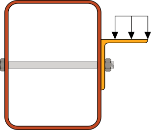
The equation in the manual (7-15) is only considering one side of the HSS to contribute to the bearing strength of the bolted connection (Apb = n*d*tdes). This would be the case for the connection shown below. The applied load will be supported almost entirely by the wall of the HSS that has the steel angle attached to it.

HSS_Through-Bolt_Connection_zi6gqm.png


I imagine that your connection configuration is one where the load is being applied equally through both sides of the HSS, in which case you would be correct that you can include both sides of the HSS in your bearing strength calculation (Apb = 2*n*d*tdes).

Structural Engineering Software: Structural Engineering Videos:
 
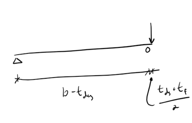
To show ProgrammingPE's example another way:

Screenshot_2022-11-28_120526_sangtk.png


Where b is the width of the wall, t[sub]des[/sub] is the design thickness of the tube, and t[sub]f[/sub] is the thickness of the fixture (angle leg in the section posted above).
 
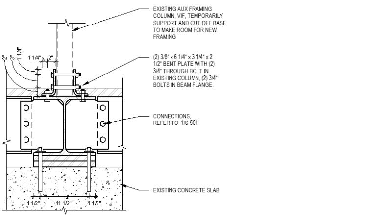
Programmer PE, yes, I am supporting an existing column for vertical load only, we need to avoid any welding in the field. Image below.

Dave and Pham, thanks for your thoughts.

IMO AISC needs to modify the language in the manual to clarify. Or better yet just delete the manual equation and refer to the specification.

Untitled_ufvqzh.png
 
Mike Mike said:
Or better yet just delete the manual equation and refer to the specification.

By that logic, the entire manual should be removed. With the exception of a few dimensional things, there's no design information in the manual that can't be derived from the equations in the specification.

I think it's quite valuable that they include it as they do in the manual. If you consider somebody in the opposite circumstance - a one sided connection but thinking the A[sub]pb[/sub] should be 2*d*t[sub]des[/sub] would over estimate the strength. But the manual equation clarifies that and helps to prevent it. We're all guilty of cook-booking it on something at sometime - as long as you stop and consider what each input means and how the equation works rather than just plugging it into the calculator, the manual as written is pretty clear on what you're checking: the capacity of a bolt through both walls of the HSS bearing on and transferring all of its load through a single wall in 'single shear' (though static bearing would be the more accurate term, 'single shear' is more relatable to most in the context of bolting).
 
Pham, let's define terms
Manual says: "The bolts are designed for static shear..."
The spec does not define static shear, but does define statically loaded: "Not subject to significant fatigue stresses. Gravity, wind and seismic loadings are considered to be static loadings."
Are you saying single shear and static bearing are the same for the purposes of this discussion? Where do you see either of these terms used in the manual or spec?
 
Single shear is a bolting term. There's a single shear plane through the bolt, and the bolt is at least snug tight in a standard bolt hole.

Static bearing is referring to a pin bearing in a hole or something similar.

Even though it is a bolt through the HSS, you don't have a nut/head combo on each wall. Without the compression on the surrounding material and resulting confinement, you can't use J3-6a/b for tear out and bearing for a bolt hole.

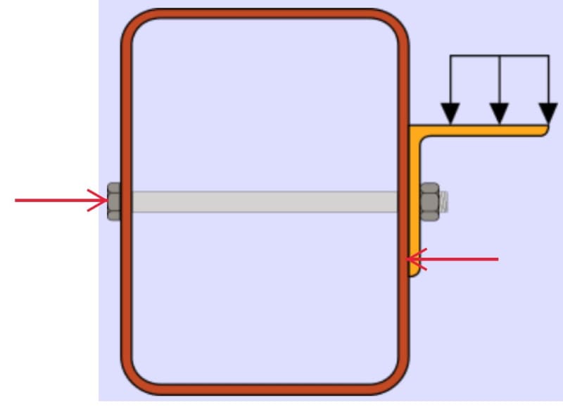
So what you have isn't a single shear bolt or a double shear bolt, you have a bolt acting like a pin that is relatively free to move around in the bolt hole. That's why you end up with the cantilever arrangement I alluded to with my FBD.
 
I am down with all these thoughts and definitions. I was not aware confinement was the reason for the different formulas in J3 and J7 but that makes a lot of sense.

The only point of disagreement that I see is in your previous comment, "the manual as written is pretty clear on what you're checking: the capacity of a bolt through both walls of the HSS bearing on and transferring all of its load through a single wall in 'single shear'". I don't see the words "single shear" or "static bearing" on manual page 7-15. I only see the words "static shear". Can you confirm you're looking at the 14th edition?
 
'Confinement' may not be the technical term in the literature, but it's how I've always made sense of it. If you confine/restrain the material from expanding out as the hole deforms, it provides more resistance in the direction of the applied force.

I am looking at the 14th, and it does say "static shear." They don't say single shear because that is fundamentally wrong...I said and used quotes because it's more relatable...I'd had my license for a couple of years (and had been through many reviews within my firm) before I picked up on the fact that these are not typical bolt problems and should use pin bearing. So while it isn't correct to call it single shear in a traditional bolt design sense, it's easier for a lot of people to visualize it that way and pedantry is rarely a good teaching tool.

But if you look at the equation, it's quite clear:

7-15 and J7-1 are identical if A[sub]pb[/sub]=d*t[sub]des[/sub], so we know that we're looking at a pin-bearing scenario. The fact that it's t[sub]des[/sub] and not 2*t[sub]des[/sub] means that only one wall of the HSS is being considered.
 
The fact that it's tdes and not 2*tdes could mean that only one wall of the HSS is being considered, or it could mean both walls of the HSS are being considered with each wall providing 0.9nFydtdes of the capacity. It's not possible to determine which interpretation is correct without the spec.

Following the instructions of the manual, I calculate the wrong answer for my scenario:
n = 2
d = 3/4"
Fy = 46ksi
tdes = .233"
so Rn = 29k

Sorry manual but the correct answer was 58k. Clearly the manual's intent is for the equation to apply to single bearing per Programmer PE's sketch, and the capacity should be multiplied by 2 for double bearing scenarios. Which sentences on page 7-15 lead you to conclude that "the manual as written is pretty clear on what you're checking: the capacity of a bolt through both walls of the HSS bearing on and transferring all of its load through a single wall in 'single shear'"?
 
Mike Mike said:
It's not possible to determine which interpretation is correct without the spec.

This is true of the entire manual. The manual is not code. The manual is not a collection of design rules. The manual is a design guide. They have assembled a lot of the most commonly used details and conditions and given general guidance on them. They took it a step further with the design examples, where they both derive many of the items in the manual using rules and equations from the spec and use a combination of the two for more specific design applications.

As it is a guide, a thorough understanding of the spec is something a prerequisite to the effective (and safe) use of the manual.

Where does 0.9nFydtdes appear in the manual/spec? If the answer is nowhere, then it's pretty clear that that interpretation is not correct.

Which sentences? Just one: "The available bearing strength is determined as phiR[sub]n[/sub] or R[sub]n[/sub]/Omega, where R[sub]n[/sub]=1.8nF[sub]y[/sub]dt[sub]design[/sub]..."

Because I'm familiar with (and as far as generalists in mid-sized metro areas are concerned, I think pretty good at) steel design, I know where bearing strength comes from, J7. Pretty easy to recognize the similarity between J7-1 and 7-15.

The manual isn't perfect, but they'll never get it so clear that it works for ever scenario every time. And if the current version has people underestimating their connections...well that's certainly better than the other way around.
 
And how are these forces accommodated?

Clipboard01_jgqwz5.jpg


-----*****-----
So strange to see the singularity approaching while the entire planet is rapidly turning into a hellscape. -John Coates

-Dik
 
Pham, "The available bearing strength is determined as phiRn or Rn/Omega, where Rn=1.8nFydtdesign..." is what lead you to conclude that "the manual as written is pretty clear ... 'single shear'"? you're right on about AISC's choice to at least be conservative: better to present a single bearing equation and not describe or sketch it than to present a double bearing equation and not describe or sketch it.

Dik hopefully you specified a thick enough wall lol
 
The tube wall looked a little thin, mind you, the angle thickness was also thin... I generally spec Loctite Red to glue the nut on the bolt, or peen the threads, too.

-----*****-----
So strange to see the singularity approaching while the entire planet is rapidly turning into a hellscape. -John Coates

-Dik
 
Status
Not open for further replies.

Part and Inventory Search

Sponsor