Eng-Tips is the largest engineering community on the Internet

Intelligent Work Forums for Engineering Professionals

  • Congratulations waross on being selected by the Eng-Tips community for having the most helpful posts in the forums last week. Way to Go!

HSS to HSS weld strength equation

Status
Not open for further replies.

wikidcool

Structural
Jun 20, 2007
50
US
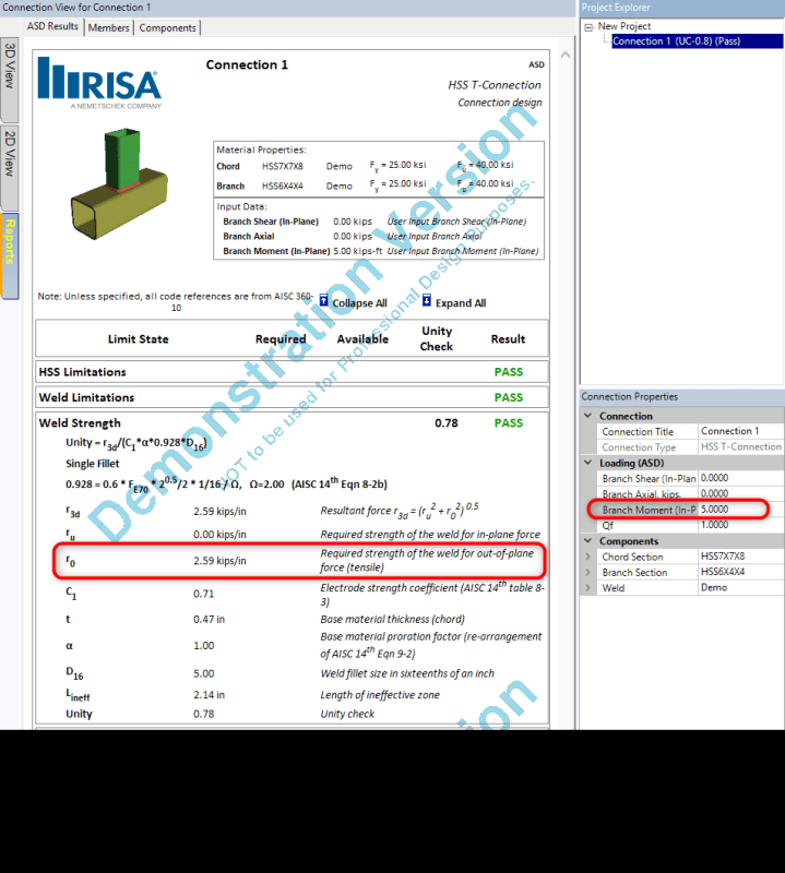
I'm working on a spreadsheet to do HSS-to-HSS "T" connections with moment loads. I have been searching and searching for something that will give an example of the weld calculation and I'm coming up empty at every turn. AISC design guide 24 example 9.2 addresses this connection great except it just says "assume the welds are sufficient". I downloaded a demo version of RISA connection to examine how they go about this, and while I've tracked down most of the process there's one important part I don't understand. They report a required weld strength "r0" with no explanation of how it's derived. By tweaking inputs, I can see that it is affected by at least the branch depth and the chord wall thickness, but I can't figure out the relationship.

See attached screengrab. For an HSS6x4x1/4 branch on an HSS7x7x1/2 chord with a 5 kip-ft in-plane moment, RISA reports a required weld strength r0 of 2.59 kip/in. Where does this come from??
RISA_Grab_hdvsta.png
 
Replies continue below

Recommended for you

Wikidcool:
You have a 5 k-ft moment on the joint, which equals 60 “k. The vert. member of the joint is an HSS 6x4x.25”, so the lever arm btwn. the two primary moment carrying welds is about 6”. Thus, the reactions or forces (ten. & comp.) at the two flanges is 60/6” = 10 k in each flg., over a width of 4”, so the weld should be good for about 2.5 k/”. Also, take a look at the books by Omer W. Blodgett, “Design of Weldments” and “Design of Welded Structures,” pub. by The Lincoln Arc Welding Foundation. He goes into considerable detail about treating a weld as a line element, finding its section properties and using those to determine the req’rd. weld for a given moment and other forces on the weld.
 
If RISA assumed an all around weld its just M/S,weld group where S is inclusive of the corner fillets which is about 23.16 in^3.
If you just weld on the workable flats of the branch then S is about 21.48 and the ro becomes 2.79 k/in

This is all based on an elastic weld analysis, for the general line weld formulas check out the elastic method section under welds in the AISC manual.

The Blodgett book suggested already is also an excellent resource.

Open Source Structural Applications:
 
Thank you both! I was totally lost and frustrated on this. I will dig deeper into those references.

dhengr, That's what I was trying to do with it too but changing the chord wall thickness in RISA changes the required weld strength/inch and RISA is also subtracting an ineffective weld-zone length of 2.14", so it appears to be more complicated than just 60 in-kip/6" arm/4" width. Celt83's use of M/S at 60 in-kips/23.16in^3 works out to exactly match RISA's math so I think the answer lies in that derivation of S for the weld group, so I'm going to chase that further.
 
FYI I had my S wrong for the condition including the fillets...actually is higher 32.93 in^3 strong and 27.23 in^3 weak

Didn't see the ineffective length value in the RISA print out which makes me think they removed the fillets and took M/s about the 6" direction which would give an S of about 23.68 in^3.

Open Source Structural Applications:
 
Take a look at specification section K4, particularly table K4.1. it goes over the effective length of welds for tube to tube connections.
 
Wikidcool:
My calcs. in my earlier post where just the first calcs. I would do, very quickly, to determine the ballpark value of loads, forces and weld size. Are the member sizes, wall thicknesses, weld sizes reasonable and adequate? That’s why I suggested you look at Blodgett’s books, to further and improve on my first calcs. Although, I might just temper those first calcs. with a bit of judgement and let it go at that. For example, I might use a weld length of only about 3.5” to account for some corner radius weld loss at max. lever arm. If you are using RISA and the latest AISC codes and guides, no doubt you can finesse the results more than my hand calcs. They will account for some plate bending in the wall of the HSS 7x7, but that’s a pretty thick pl. at .5”.
 
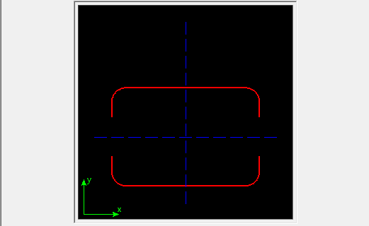
structSU10 I'm admittedly not familiar with this portion of AISC does the ineffective length apply across the HSS wall such that you get an effective weld group per below, due to the flexibility of the wall under the perpendicular loading caused by the moment?

Capture_a9yaey.png


Open Source Structural Applications:
 
It depends on the branch type it can be considered - basically the forces applied at the joint. What you show is applicable to some branch types, and i think it is applicable to your situation, but it may not apply to all branch types. I believe RISA is reporting the ineffective length based on these equations.
 
Status
Not open for further replies.

Part and Inventory Search

Sponsor

Back
Top