Continue to Site

Eng-Tips is the largest engineering community on the Internet

Intelligent Work Forums for Engineering Professionals

  • Congratulations KootK on being selected by the Eng-Tips community for having the most helpful posts in the forums last week. Way to Go!

HSS top chord effective compression bucking length 1

Status
Not open for further replies.

leetse

Structural
Mar 29, 2015
6
Hello all,

HSS Truss supporting a concrete slab on deck which is puddle welded to the top chord. Top Chord is in compression. I have always assumed that the in-plane compression buckling length for the top chord, is the distance between panel points.

A fellow engineers opinion is that the slab will restrain the top chord fully both in plane and out of plane. Is there any available guidance about this available?
 
Replies continue below

Recommended for you

For typical proportions of slab and truss chord, the slab will provide lateral bracing. Thus for chord out-of-plane buckling, the unbraced length would be zero.

For in-plane buckling, it's a little trickier. The slab bending stiffness restrains in-plane buckling, but you would need a fairly sophisticated analysis to consider it. Typically, I would do as you've suggested: the unbraced length equals the distance between panel points.

The only reference I'm aware of is the AISC Specification Appendix 6.

It sounds like your colleague(s) are envisioning a thick slab with a small truss. If the slab is thin and the truss is huge, the truss would barely "know" the slab is there, so the slab restraint wouldn't play much of a role.
 
How much difference is it making to the capacity?
 
The difference is meaning that a HSS6x6x1/2 is just overstressed. Therefore means going up a HSS series size, and relooking at the connections unless a sharper pencil and a review of the loads is undertaken. I will look at the App 6 thanks. The slab is 5 1/2" on a 3" deck so it is substantial compared to the chord size. Thanks for the replies.
 
Seems reasonable to assume it’ll provide some restraint. How do you imagine it buckling?
 
If the unbraced length is the length between panel points then what is the strength ratio?
 
You might try the following simplified analysis.

Transform the effective width of slab to steel. Compute its transformed moment of inertia about its own centroidal axis. Add that to the HSS moment of inertia. (Don't include parallel axis terms because the slab plus HSS section won't be composite.)

Compute the elastic buckling load with this new MOI: Pe = pi^2 * E * I / L^2, where E is the elastic modulus of steel and L is the distance between panel points.

Divide Pe by the HSS + transformed slab area to get Fe to use in place of Eq. E3-4.

Proceed with the Section E3 equations with only the HSS section properties to get Pn.
 
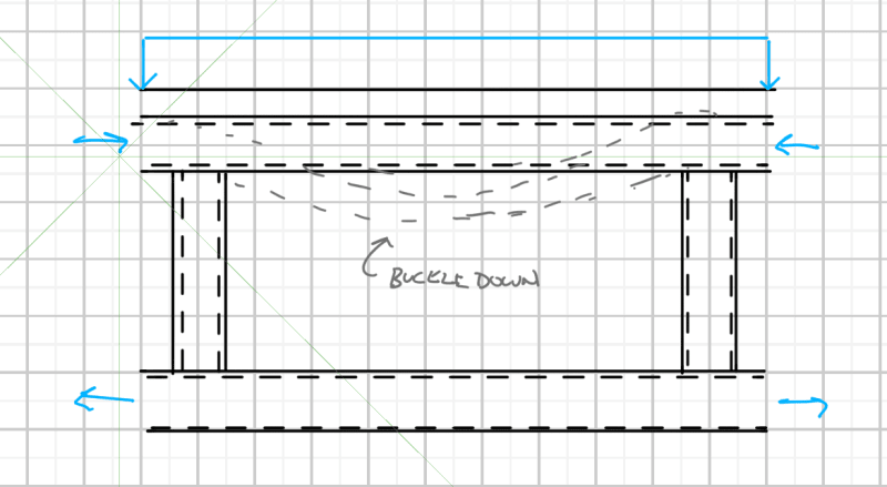
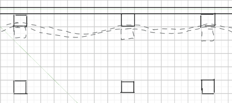
I imagine it buckling down and then you are relying on the puddle weld in tension, which I was unsure if this was legit?
 
You have the weight of the slab bearing down on the chord. That alone will help.
 
I'd want to know a fair bit more detail about how this is being analysed before I start relying on the slab for in plane restraint of the truss chord. This really requires a full buckling analysis.

I did a quick buckling analysis with a few assumptions about the truss and the results showed that the slab is not sufficiently stiff enough to rely upon as a continuous restraint.
 
You could probably make a PhD out of this, by the barrel-scraping standards of today. But for design, I'd treat it as a lean-on (or pull-on) buckling problem. Agent666's blog has a post on the subject.


I suspect 271828's method is equivalent but using stresses instead of forces.

Given the proportions, I don't think the slab necessarily precludes buckling of the chord in the plane of the truss. The slab stiffness is similar to the chord stiffness, not orders of magnitude greater. Stiffness is the first key issue. You need to consider the potential for cracking in the slab's transverse direction due to the loading on the deck, ie cracks that aren't parallel to the truss. If all the chord load were sustained, creep would also come into it, but not if there's a decent reduction from short-term to sustained chord force as the lean-on force will fall away quickly when the chord isn't close to buckling.

The second issue is making sure the connections between slab and truss are in effective positions. You want some connections midway between the panel points so the chord can pull on the slab if it buckles away, and also connections near the panel points so the slab has a reaction point for the case where the chord buckles towards the slab.

Lastly, you need enough strength and stiffness locally in those connections. I'm picturing the metal deck provides little stiffness in the slab's transverse direction (parallel to the truss) due to thin cross-section without corrugations that way. So you need to be confident the concrete is engaged if the chord is pulling away from the slab, both at the panel points or midway between. Some deck profiles don't give me much confidence of that but maybe there's literature. Also, how far does that thin sheet need to span from a puddle weld to a corrugation?

The good news is that restraint forces are fairly small, so most systems have some chance of functioning as bracing, at least partial bracing (see Agent666's first example).
 
Steve said:
The slab stiffness is similar to the chord stiffness, not orders of magnitude greater.

The slab will be close to an order of magnitude stiffer. Also, the slab needn’t make it impossible to buckle. All the slab need do is increase the buckling load somewhat, given that the current buckling load falls only slightly short of what’s required.


Steve said:
You want some connections midway between the panel points so the chord can pull on the slab if it buckles away

The alternating half waves are trying to push up, against the slab. It’s being constrained that way too. As it is people seem to be envisaging the buckling chord lifting the slab upwards.
 
Tomfh said:
The slab will be close to an order of magnitude stiffer.
I'd want to know more about the slab before I jump to that conclusion. If it is one way span perpendicular to the truss then it might be surprisingly flexible in the bending plane of the truss.

Tomfh said:
Also, the slab needn’t make it impossible to buckle. All the slab need do is increase the buckling load somewhat, given that the current buckling load falls only slightly short of what’s required.
Very true. But that doesn't make it correct to assume that it is continuously restrained by the slab. In fact it is damn WRONG. It is an inaccurate assumption that might not cause a problem here but could if the same logic is applied in another circumstance.

It would be advisable to perform a rational buckling analysis. Not just proclaim that the slab/deck is 'stiff enough' when it really isn't.
 
Human909 said:
If it is one way span perpendicular to the truss then it might be surprisingly flexible in the bending plane of the truss.

Leetse, please post some of the details.


Human909 said:
But that doesn't make it correct to assume that it is continuously restrained by the slab. In fact it is damn WRONG

I’m not saying it’s continuously restrained. It needn’t be continuously restrained. It just needs a bit of extra restraint, which the clamping effect of the slab will likely provide.
 
I would think the loading from the slab to the top chord would initiate a downward buckling mode and since this is likely a system of trusses all wanting to buckle downward the slab would really just go along for the ride and not provide very much if any restraint, I'd land on treating this like a wood stud in a stud wall the sheathing can brace the out of plane buckling but in plane it has little effect so the unbraced length is the full stud height.

Panel without diagonals shown:
Screenshot_2023-01-09_104712_hfkdso.png


System of trusses and slab with the top (compression chord) all buckling downward:
Screenshot_2023-01-09_104730_kyfvwn.png
 
Tomfh said:
The slab will be close to an order of magnitude stiffer. Also, the slab needn’t make it impossible to buckle. All the slab need do is increase the buckling load somewhat, given that the current buckling load falls only slightly short of what’s required.
6 feet of slab is about the same section stiffness as the SHS assuming cracked. I don't know for sure that it will be cracked as we have no details, but the section modulus in the transverse direction is about half of the modulus in the span direction and some deck profiles look like crack starters to me. It's probably getting up there unless the main slab span was designed to be uncracked at ULS design load.

Re impossible to buckle: The question was initially that the colleague says the slab fully restrains the chord and that's what I was referring to when saying buckling isn't precluded.


Tomfh said:
The alternating half waves are trying to push up, against the slab. It’s being constrained that way too. As it is people seem to be envisaging the buckling chord lifting the slab upwards.
Maybe. It looks like the top half of a scissor jack to me. Also, weight doesn't add stiffness - you're still pushing against EI which is why I think the slab needs to be connected in a way that it becomes a strongback to the chord.


I ran buckling analyses of UDL on a truss top chord vs point loads at the chord-diagonal intersections. The UDL had slightly lower elastic buckling load (a few %) which I think is due to the initial bending in the chord pushing it slightly out of shape.

trussUDL_f8n9di.png
 
Steve said:
6 feet of slab is about the same section stiffness as the SHS assuming cracked.

What have you based that on? Maybe it is only similar stiffness to the SHS…

Steve said:
I ran buckling analyses of UDL on a truss top chord vs point loads at the chord-diagonal intersections.

I was referring to was the downwards clamping force from the weight of the slab. For the chord to buckle it has to begin lifting the slab. So as well as fighting against EI, the buckle is fighting against gravity.
 
Tomfh said:
For the chord to buckle it has to begin lifting the slab. So as well as fighting against EI, the buckle is fighting against gravity.
Or it could just buckle in the opposite direction assisted by the weight of the slab and P-delta effects....

Sure you might be assuming the slab is stiffer in this direction. That is likely true. However we still are not orders of magnitude stiffer.

Tomfh said:
I’m not saying it’s continuously restrained. It needn’t be continuously restrained. It just needs a bit of extra restraint, which the clamping effect of the slab will likely provide.
I agree. But the degree of extra restraint needs to be well defined and quantified before we start jumping to conclusions that the design is satisfactory. My approach would be a rational buckling analysis approach with my available computational tools.
 
Human said:
Or it could just buckle in the opposite direction assisted by the weight of the slab and P-delta effects....

For the primary in-plane buckling mode you will have alternating up/down/up/down buckles between the nodes.

This mode is constrained if the upwards buckles are constrained.


I agree with you guys that it should be quantified in some way. I’d just be surprised if the slab doesn’t get it over the line. OP suggests it’s pretty close with no restraint.
 
Status
Not open for further replies.

Part and Inventory Search

Sponsor