Continue to Site

Eng-Tips is the largest engineering community on the Internet

Intelligent Work Forums for Engineering Professionals

  • Congratulations waross on being selected by the Eng-Tips community for having the most helpful posts in the forums last week. Way to Go!

Hydraulic Cushioning Valve Configuration

Status
Not open for further replies.

SGCE412

Industrial
Apr 26, 2017
1
Hello All. New here, and new to hydraulic circuit design. I would like some feedback on the cushioning valve configuration shown in the attached schematic. I'm working on a system with hydraulics that are used to lift large mixing bowls which sometimes are abruptly stopped (safety mat trigger). In all the reading and examples of how to use cushioning valves, I have yet to see a circuit as the one on this machine. Is it correct? Is it doing something I don't understand?

Note: The cushion valves themselves appear to be drawn incorrectly, in that the pressure lines are not dashed, and the valve is shown such that flow through it is the normal position.
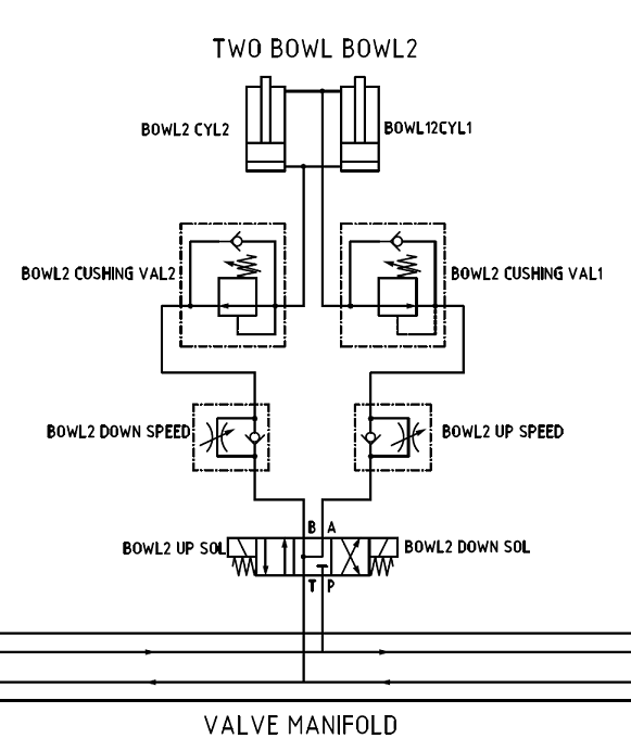
Cushion_Valve_Circuit_e3focr.png
 
Replies continue below

Recommended for you

The drawing is wrong...very wrong actually.

The cushion valves are also known as counterbalance valves. They should be drawn as relief valves that are opened by upstream pressure at the cylinder.

The check valve should allow free oil flow to the cylinder and should block the oil flow coming from the cylinder.

 
Also, placing two cylinders in parallel (hydraulically) and using one speed control valve is not a good practice unless there is a mechanical linkage between the cylinders to keep them synchronized.
 
Bowl2 doesn't look right. What is it supposed to do? It isn't relieving to anywhere.

Why not move into the 2100s? Relief valves will not anticipate the impact and limit the impact forces.

Even if 100% retract signal is applied to a servo valve when the pressure or force reaches the set point the valve will NOT respond in time.

We control 4 axis cushions. Each axis has a servo quality valve. There is NO WAY relief valves are going to limit the impact. The relief valves do not respond quickly enough. Neither will servo valves UNLESS you anticipate the impact.

Limiting the impact force is similar to a base ball catcher moving his mitt backwards in anticipation of impact. On top of that the impacts can be simulated and therefore controlled.

We have done research on controlling impacts. We can gather positions, velocities, pressures and forces at 1 millisecond or faster. Without this information one is designing in a vacuum.


Peter Nachtwey
Delta Computer Systems
 
Status
Not open for further replies.

Part and Inventory Search

Sponsor