Eng-Tips is the largest engineering community on the Internet

Intelligent Work Forums for Engineering Professionals

HYDRAULIC DAMPING - TRY TO UNDERSTAND THE DIAGRAM

Status
Not open for further replies.

BEMPE16524

Mechanical
Feb 17, 2008
277
0
0
SG
Hi Guys,

I have a system as in following image:
snubber_damping_A-FRAME_btg60a.png

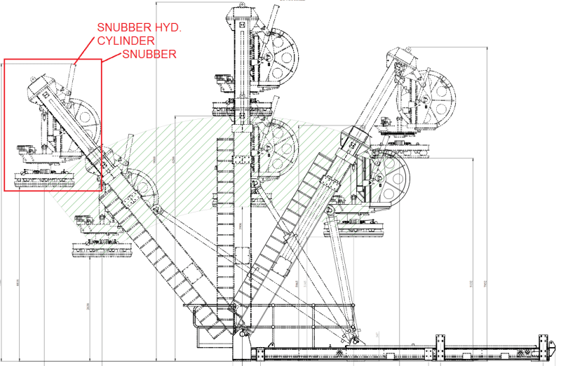
it is a launch and recovery system (LARS). the snubber will carry a suspension load and move together with the LARS leg (luff in/out).
the operating pressure is around 210Bar.

So I'm trying to understand the hydraulic diagram here but I still cannot digest the logic behind it (especially the damping valve):
snubber_damping_pwbszo.png

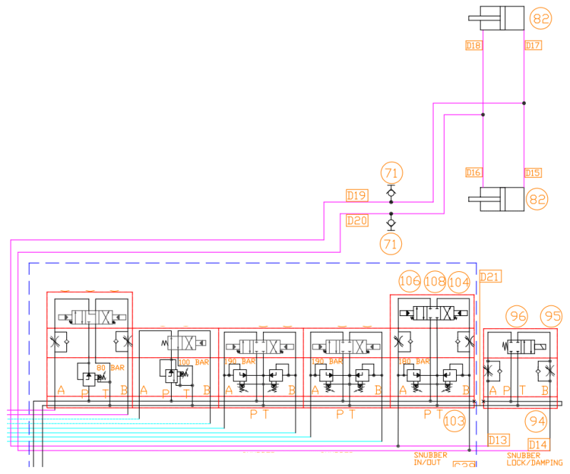
I have no issue with the 'snubber in/out' part.

but the 'snubber lock/damping', how does it work actually? is the solenoid valve switch on together with the one on the 'snubber in/out'?

R.Efendy
 
Replies continue below

Recommended for you

The valves on the left control the extend and retract of the damping cylinder. The idea being that the recovered item, boat or buoy or whatever, is pulled up against the damper. Or, it is offering some controlled "docking" when the assembly is luffed.

The valve on the right, when not operated, will make the damper rigid. When the valve on the right is operated, it makes a primitive regen circuit and connects the rod of the damper cylinder to the head. The flow control valves limit the flow of the oil through the circuit and control the amount of damping.

 
after cross check with the remote control, I understand more on what you said.
FluidPowerUser said:
The valves on the left control the extend and retract of the damping cylinder. The idea being that the recovered item, boat or buoy or whatever, is pulled up against the damper. Or, it is offering some controlled "docking" when the assembly is luffed.

The valve on the right, when not operated, will make the damper rigid. When the valve on the right is operated, it makes a primitive regen circuit and connects the rod of the damper cylinder to the head. The flow control valves limit the flow of the oil through the circuit and control the amount of damping.

snubber_damping_remote_wzppqf.png


that means in order to provide the damper (or slowing down the motion), I need to activate the solenoid valve when operating the 'snubber in/out'.

Thank you for that.


R.Efendy
 
Snubbing switch will move the cylinder in and out

Damp/lock will do as it says. Either dampen the operation or lock the cylinder.

The valves will operate independently of each other. In other words, one will operate the direction and one will turn on the damping, you don't need to operate them at the same time.
 
FluidPowerUser said:
When the valve on the right is operated, it makes a primitive regen circuit and connects the rod of the damper cylinder to the head.

I'm not sure about the regen part, it looks like both A and B dumps to tank. The tankline is connected and the P is also connected to the tankline.
 
Status
Not open for further replies.
Back
Top