BEMPE16524
Mechanical
- Feb 17, 2008
- 327
Hi Guys,
First of all i'm sorry i don't have complete information of this old system. Please see my attachment for overall hydraulic schematic (you can download the pdf too).
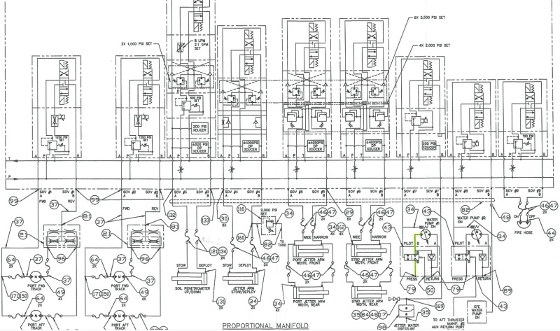
I have a problem to understand how the system function. I understand how the solenoid valve (SOV 7 and 8) operated but on the manifold, i cannot figure out how it is operated.
From my view, when the SOV is energized, it will direct the oil from P to A and straight to the manifold.
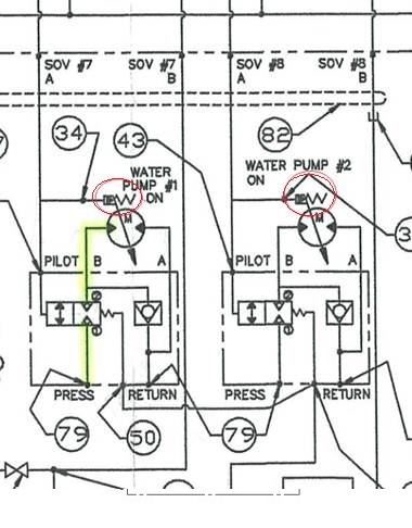
From here i'm not sure, does it operated the valve (34) thus turn on the pump? at the same time it go to pilot (43) and energize the internal valve?
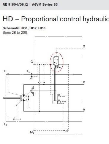
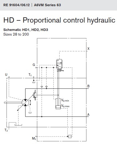
What is valve 34? Is it just a connection to point 'x' in the hydraulic motor (pump) schematic as i found the model is Rextroth AA6VM55HD2/63W-VSD510A.
What is valve in red circle?
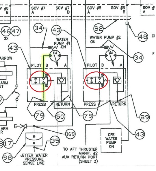
Can someone help me explain how these two banks work please.
R.Efendy
First of all i'm sorry i don't have complete information of this old system. Please see my attachment for overall hydraulic schematic (you can download the pdf too).

I have a problem to understand how the system function. I understand how the solenoid valve (SOV 7 and 8) operated but on the manifold, i cannot figure out how it is operated.
From my view, when the SOV is energized, it will direct the oil from P to A and straight to the manifold.
From here i'm not sure, does it operated the valve (34) thus turn on the pump? at the same time it go to pilot (43) and energize the internal valve?
What is valve 34? Is it just a connection to point 'x' in the hydraulic motor (pump) schematic as i found the model is Rextroth AA6VM55HD2/63W-VSD510A.

What is valve in red circle?

Can someone help me explain how these two banks work please.
R.Efendy

