Eng-Tips is the largest engineering community on the Internet

Intelligent Work Forums for Engineering Professionals

Hydraulics of bellmouths on discharge pipe

Status
Not open for further replies.

AusMike

Chemical
Feb 23, 2024
2
0
0
AU
Hi all.

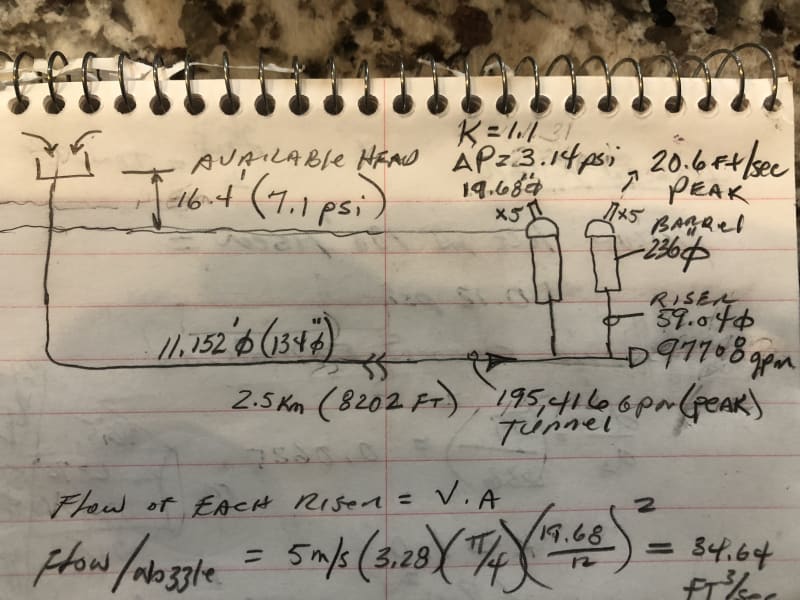
We operate an undersea outfall that has a 1.5m diameter riser pipe discharging by gravity vertically into a 6.0m diameter barrel with a diffuser cap on top, discharging to the ocean.

The outfall capacity needs to be doubled and I have suggested installing bellmouths on top of the risers inside the barrels will reduce the headloss and hence allow more flow at any particular upstream water level.

My thoughts are that gradually slowing the velocity through a bellmouth (say double the riser diameter at the outlet) will significantly reduce the headloss compared to an open exit (1.5m from the riser straight into the 6.0m barrel).

Another engineer has suggested bellmouths don't do anything for headloss on outlets - only inlets.

What do others think?

Thanks
AusMike
 
Replies continue below

Recommended for you

He's right, because you are going from some piping velocity to a velocity of zero in the large body of water a pipe exit will always have a K factor of 1.

EDIT: I made the same mistake your colleague did. While K = 1.0 for all pipe exits meaning that the head loss is one velocity head, a larger pipe exit gives lower velocity - less velocity head - so lower head loss.
 
See the narrative on page 6-17 in Perry Chem Engg Handbook 7th edn. Where the angle of divergence of the expander fitting is greater than 35-45deg, the K factor is the same as that for a sudden expansion. For trumpet shaped expanders, pressure drop is lower.
 
Also seems to depend on whether this is laminar flow or turbulent. Which is it?

And if you expand the end will it become laminar flow?

Laminar them a gentle curve expanding at about 20% seems to be lowest losses.

Remember - More details = better answers
Also: If you get a response it's polite to respond to it.
 
It depends to a large extent on the length of the line and what percentage of the overall pressure drop is consumed by the exit loss. If you have a long line and the exit loses only 1% of the pressure drop and you are somehow able to eliminate the exit loss completely you have 1% additional pressure available to drive more flow. And since the pressure is (roughly) proportional to the square of the flow you would increase the flow by 0.5%.

Even a short line with 10% of the total pressure being lost at the exit would achieve only 5% more flow by eliminating the exit loss.

To be in the laminar flow range for a 1500 mm pipe you need a velocity of about 2 mm/s (yes, that is millimeters per second)!

Katmar Software - AioFlo Pipe Hydraulics

"An undefined problem has an infinite number of solutions"
 
I knew it (laminar flow) was pretty slow but that's unreal....

But agree with Katnar, these losses are normally really quite a small part of any overall frictional losses.

What exactly do you mean by" discharging by gravity??" Got a sketch of this arrangement?

Remember - More details = better answers
Also: If you get a response it's polite to respond to it.
 
Thanks LittleInch.

It's a 2.5km long 3.4m diameter tunnel with two 1.5m risers, 6m diameter barrels and nozzle caps on each barrel. Each barrel has five 0.5m diameter nozzles to produce >5m/s velocity for diffusion.

A gravity shaft drives the flow through the system. The higher the tide and the higher the flow, the higher the water level in the gravity shaft. There is a limit on the top water level in the shaft, because a number of streams - big and small - have to overflow to the shaft, and ideally they can continue to flow downhill to get there. We don't want to have to pump big flows to the shaft unless it is unavoidable.

The total head loss at peak flow is only about 5m, of which 1/3 is in the tunnel and risers, 1/3 is the riser open outlet into the barrel and the inlet to the diffusers, and 1/3 is in the high velocity diffuser outlets.

We can't do much about the 1/3 of the loss in the tunnel or the 1/3 of the loss in the nozzles.
This leaves the 1/3 that is up for grabs - the sum of the losses from the riser outlet (k=1) and the sharp edge nozzle inlets (k=0.5). I'm proposing bellmouths on both.

If I'm not mistaken, the open outlet loss into the barrel will drop significantly, because, although it is still an open outlet with a k value of 1, the velocity at double the diameter will go from about 3.5 m/s to 0.9 m/s. The v2/2g loss should be 1/16 of the original if we double the diameter shouldn't it?

If we put bellmouths on the inlet side of each diffuser pipe, a sharp edge k value goes from 0.5 to a bellmouth at 0.05, which makes a big difference at 5m/s fluid velocity.

If this works, it will buy us enough gravity flow capacity at high tide so we won't have to construct more risers out in the ocean under 25m of water ($$$$$).
 
Many gravity atmospheric flow lines run two phase liquid-air (line is not liquid full), this usually happens when the static differential pressure is much higher than the frictional drop.
 
LittleInch's tagline of "More details = better answers" is very relevant here. For those of us who are not experts in sea outfall design the description is rather confusing. It seems to me that the correct place to get the most benefit from bellmouth reducers would be to use them where the 1.5m diameter risers connect to the 3.4m diameter tunnel. Shaped reducers are much more effective when the flow is from the large diameter towards the small diameter than the other way around. But I might have completely the wrong flowsheet in my mind.

Maybe I need to add an "and most of them are wrong" to my tagline.

Katmar Software - AioFlo Pipe Hydraulics

"An undefined problem has an infinite number of solutions"
 
Something doesn't add up here for me.

From your data you have 5m head in total, but flow in your tunnel is about 2m/sec, but at 2.5km only has a 1.5m pressure drop?

Don't forget that to double flow, your losses increase by a factor of 4 in your tunnel and risers.

I can't see bellmouths on exit into this mysterious barrel and nozzles adding more than 10% capacity without altering your overall head loss.

This is pretty big stuff here, I calculated about 12m3/ sec.

But to double it without raising the inlet you're going to need a pump or build another one...

Remember - More details = better answers
Also: If you get a response it's polite to respond to it.
 
Based on my understanding of how your system is configured here is the results of my calculations. My calculations are based on the following assumptions:

Peak flowrate is 97708 GPM per riser based on your statement that peak flow gives 3.5 m/s in risers.
Specific Gravity of Liquid = 1.0
K factor for nozzles = 1.1

Calculation of pipe pressure drop using darcy equations for new steel pipe.

Inside pipe diameters considered as pipe diameters indicated.

Pressure Drops:

Nozzles = 3.14 psi (assumed K = 1.1 where 0.1 accounts for friction loss and 1.0 accounts for exit velocity head, 19,542 GPM per nozzle)
Inlet to Nozzles = 1.43 psi (based on sudden contraction K = 0.5)
Barrel pressure loss = negligible (at 0.72 fps)
Loss in Riser = 0.19 psi (based on 100 ft length at 11.45 fps)
Loss in Riser Outlet to Barrel = 0.88 psi (based on K = 1.0 at 11.45 fps based on sudden expansion)
Loss in 2.5 km Tunnel/Pipeline = 0.99 psi (at 195,420 GPM)

Total pressure drop = 6.63 psi

As you indicated the only place to reduce pressure drop is inlet to nozzles and outlet of riser to barrels.

I believe if you change the inlet to the nozzles to a rounded entrance then you can eliminate most of this inlet loss of 1.43 psi. A very rounded inlet gives very low K values. Also if you increase the take off hole diameter to very large and gradually reduce to the nozzle diameter this may also reduce the pressure drop here if it is too difficult to fabricate or procure a rounded inlet.

For the outlet of riser to barrels I believe that in any case with a bellmouth or short increaser at exit the ratio of diameters will not change so 1.0 (1-(d1/d2)[sup]2[/sup]) K value does not significantly change by increasing the diameter of the riser with a bellmouth fitting or a single short increaser. Think of it as the exiting velocity will still be basically a jet based on the velocity in the riser, not based on the exist area of the bellmouth (flow will not conform to the increased exit but will still be a jet base on riser diameter), with headloss = 1.0 (V[sup]2[/sup]/2g) of riser so increasing 2x area with bellmouth or short increaser will still give a jet the diameter of the riser that will exist into the barrel causing similar pressure drop as a sudden expansion in my opinion. I believe most to the pressure loss for sudden enlargement is in the dissipation of the kinetic energy of the jet in a disorderly manner inside the larger pipe fluid across the suddden expansion rather than gradually reversibly converting the kinetic energy of the upstream side to pressure head (like is normally done in a increase like in a pipe since that is short yes but diameter change is not large).

I think what you need to do is install a gradual increaser at the connection of the riser to the barrel over a significant distance, maybe a series of increasers so that the flow really goes from a velocity of 11.4 ft/sec to much lower in an orderly manner so that the velocity really is the based on the ratio of areas at exit of riser to the barrel. Note that for a low pressure drop reducer/increaser the angle of the sides of the reducer makes from the smaller diameter to the larger diameter is 45 degrees or less, therefore length of reducer/increaser would be a minimum of 6 feet long if one increaser. I would make it maybe 9 ft long with multiple incresers to be conservative.

Also possibly you can tap into the tunnel and install and additional riser to each barrel if that is possible which would also reduce the velocity at connection by 2 and friction loss by a factor of 4.

Note that if you do not increase nozzle size but flowrate increases significantly then you will be back where you started from with new pressure drop in nozzles being higher to negate the benefit of making any of the other changes you could make to reduce the pressure since the nozzles are where most of your pressure drop occurs.


Here is a sketch of the system that I made based on my understanding of how it was described.

IMG_1542_wdendh.jpg
 
Snickster's flowsheet is exactly what I had in mind when I suggested that the best benefit from installing bellmouth reducers would be where the risers connect to the 3.4m diameter tunnel. I still believe that is true, but the benefit in terms of additional flow will be very small.

Katmar Software - AioFlo Pipe Hydraulics

"An undefined problem has an infinite number of solutions"
 
When there isnt sufficient replacement air to account for the air entrained in 2phase gravity flow lines, flow just reduces to match the available air. One then gets the false observation there is high pressure drop.
 
@georgeverghese - do you agree with the flowsheet given by Snickster? If yes, then the only point where air can enter is at the start of the line shown in the top left corner of his sketch. If Snickster's estimate of the flowrate is correct (which I have not tried to verify) then the flow of 195,000 USgpm gives a velocity in the 3.5 m tunnel of 1.3 m/s or 4.3 ft/s. This makes the Froude Number 0.22 and the vertical leg will be self venting (Fr < 0.31). But if the target is to double the flow then this would cause the problem you have described. Where do you anticipate the problem occurring?

Katmar Software - AioFlo Pipe Hydraulics

"An undefined problem has an infinite number of solutions"
 
It's the 1 psi pressure drop in the 2.5km tunnel which I can't get my head around....

This line almost certainly isn't flat either.

We don't know what the max height there is in the shaft above sea level. That will be the limiting factor by the sound of it.

Remember - More details = better answers
Also: If you get a response it's polite to respond to it.
 
@katmar, it doesnt seem to match the description from @ausmike. Think the flow from this 3400mm dia gravity flow line flows directly into the 2nos of 1500mm dia riser pipes which then lead into the 6m barrels fitted with these diffusers.
@ausmike ought to provide a sketch, with relevant details on elevations - I'd wait till I see this. The more detail, the better. And what do you mean by "gravity shaft" ?
 
Status
Not open for further replies.
Back
Top