Continue to Site

Eng-Tips is the largest engineering community on the Internet

Intelligent Work Forums for Engineering Professionals

  • Congratulations waross on being selected by the Eng-Tips community for having the most helpful posts in the forums last week. Way to Go!

I am looking for a rotating joint 3

Status
Not open for further replies.

knowlittle

Materials
Jul 26, 2007
192
DRIVING rod: This rod is making a simple in-out movement. 4" (10 cm) movement.
DRIVEN rod: This rod follows DRIVING. This rod also rotates (2 revolutions).
Both rods are about 1" (2.5 cm) in diameter. End surface of the rods has a tapped hole, on the axis of the rod.

I need a joint that connects the two, transferring 4" movement from DRIVING to DRIVEN, allowing DRIVEN to rotate. DRIVING does not rotate. I can drill/tap additional holes to both rods. I can modify both rods.

 
Replies continue below

Recommended for you

I'm desperately trying to make a truth table in my head of what you're trying to do. And it isn't coming easily.

DriveR: reciprocating linear movement (4"), 1" diameter
DriveN: reciprocating linear movement (4"), 1" diameter, also rotates (2 revolutions, whatever that means?)

I'm taking a complete shot in the dark and I'm just going to leave you with the term "Barrel Cam".

You need to be more specific on what you're trying to do, preferably with a diagram.


The driven rotates because it has spiral grooves , so at the end connection between driven and driver, there will be a rotating joint which will allow rotation and translation.
 
I'm not sure the straight spherical ball joint does what the poster is looking for. If his machine is anything like the youtube video, I think a bearing assembly of some kind is called for.

Are the driven rod and driving rods collinear?

If so, I would be looking at some kind of coupling assembly where the driven rod is fixed to the inner race of an angular contact bearing, and the driving rod is fixed to the outer race. Another possibility is a spring loaded assembly using thrust bearings between the fixed and rotating surfaces.
 
Could the joint be larger than the rod diameter?
What loads and "rpm" are involved?


Indepenedent front suspension ball joint. One handles radial and axial (holding up the car) forces, the other (in a non macphersone strut suspension) one handle primarily radial forces.
Rotates thru ~ 90 degrees, but that is limited by the rest of the car, not the ball joint.
Suspension Ball joints can Transmit axial force primarily in one direction based on suspension design, but often are preloaded with springs, etc for zero clearance, which might result in quite modest axial capacity in the "wrong" direction.

If the shafts are not aligned VERY well coaxially the ball joint would be subjected to radial forces, which it would resist strenuously.

Some kind of a flat faced washer in place ot the ball would allow radial shift.
 
Mintjulep
I checked the straight spherical joint. It allows rotations/pivots but is not designed to allow 4 rotations in a second (2 CW and 2 CCW). I need a bearing of some kind.

sensij1,
Yes, both DriveR and DriveN are colinear. I plan to use a pneumatic cylinder (double acting) as the DriveR.

tmoose,
The joint I am looking for needs to be capable of 4 revolutions a second.

I need a bearing-based joint. If there is off-the-shelf type available, please let me know. Thanks.


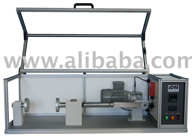
Gelbo_Flex_Tester.jpg


I can imagine a few ways to accomplish this.
 
If I were going to design this from scratch I'd probably use a shaft with a self-reversing screw on one end and drive it through a ball spline on the other. Single shaft. No joint required.
 
I don't know what is a self reversing screw. But if your design can be implemented with off-the-shelf items, please advise. I haven't bought anything yet. Thanks.
 
Okay, I watched youtube for self reversing screw and ball spline. Still I fail to see the connection between these two and what I need to achieve. Please advise.
 
You are not likely to find a totally "off-the-shelf" solution.

But there are many suppliers of custom lead screw shafts and linear motion components that could supply what you need, either to your drawings, or design what you need if you give them quantifiable criteria.
 
Are you trying to design a test machine like the one shown in your first YouTube link or my picture?
 
Yes, I need a tester in the youtube link or your photo. My plan is to buy the shaft with a helical groove and build around it. But if you have a better approach, I am listening. I have a machine shop supporting me. Unfortuately I am not an ME.
 
Looking at the picture I posted earlier:

Rotating motor drives gearbox drives crank arm.

Crank arm has a combination clevis and thrust bearing that imparts a oscillating linear motion to the shaft.

The shaft has a lead screw thread on the opposite end that reacts against a fixed nut to create the rotation.

My suggestion:

Motor drives hollow-quill gearbox with ball spline nut mounted to the gearbox.

Ball spline nut drives ball spline on one end of the shaft. This imparts rotation to the shaft.

The other end has a self-reversing screw thread. The reaction of the nut on the thread imparts the linear oscillating motion.

 
Thanks. I see it now. I will present your suggestion to the machine shop and have them choose.
 
Status
Not open for further replies.

Part and Inventory Search

Sponsor