Continue to Site

Eng-Tips is the largest engineering community on the Internet

Intelligent Work Forums for Engineering Professionals

  • Congratulations cowski on being selected by the Eng-Tips community for having the most helpful posts in the forums last week. Way to Go!

I-Beam LTB Length at support under hogging moment 2

Status
Not open for further replies.
Hi

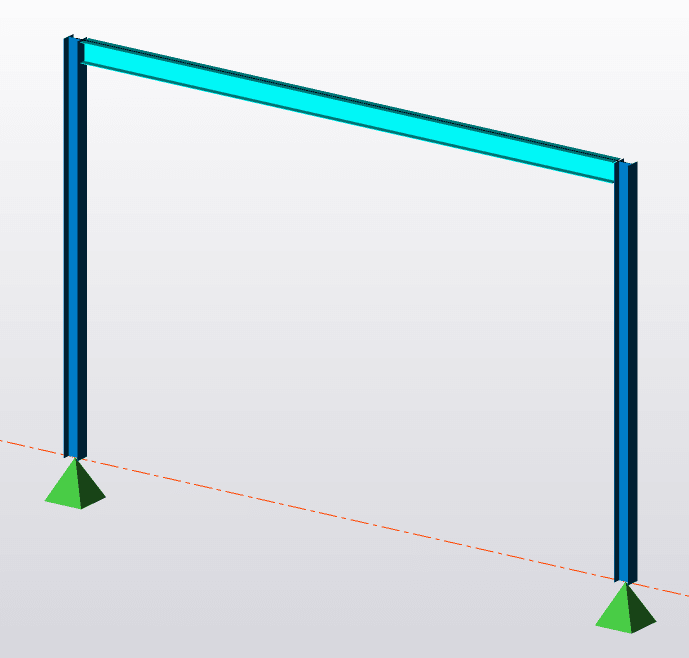
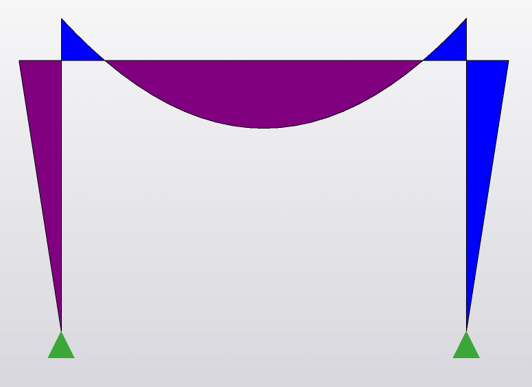
If I have a very simple steel frame with 2 steel columns and one 1 I-beam (UB) and BMD as shown below, how do I decide my beam critical length for LTB resistance at support under hogging moment? My software is using full span length but I was wondering whether it should be shorter as my bottom flange at mid-span will be under tension. Should it be the length from maximum moment to zero moment (point of contraflexure)?

Capture_upjoic.png
Capture1_llbist.png


Thanks
 
Do you want the long version or the summary?
 
struggle - to boil it down to simplistic terms, LTB is more-or-less caused by the compression flange buckling like a column. When you consider column buckling, what do you use for your length? I realize you can "shorten" it with a K factor for fixity, but keep in mind that the K factor looks at fixity in the direction of buckling. In this case, you likely have a pin in the week axis while your strong axis is fixed. So lateral buckling of the "column" that is your compression flange would have a K = 1.

If you have a diaphragm or discreet braces, you can reduce your lu. Otherwise, it's the distance between the columns.
 
1) In most practical situations, your beam will have some bracing which will have a large effect on LTB. If you'd like us to consider something other than a completely unbraced beam, you'll have to let us know what you're really working with here. It's very common, for example, to have tightly spaced bracing on the top flange.

2) A long version of the LTB story can be found here: Link. There is some truly excellent information in there if you have the patience for it.

3) To some extent, the answer to your question depends on what steel code you're using (US / Aussie / Eurocode). The approaches taken for LTB in those standards are not always identical.

4) The fact that much of your bottom flange will be in tension will indeed have a massive impact on your LTB capacity, for the better. We studied that explicitly, and numerically, in the thread that I referenced.

5) It sounds as though you are going down the road of wondering whether or not your inflection points can be considered to be LTB bracing. That is certainly not the case in North American practice and you can find an excellent article about that here: Link. Basically, [K] values need to reflect the actual shape that the bottom flange would assume when it buckles laterally as part of the LTB phenomenon. And inflection points do not convert the buckling shape into three half sine waves as one would expect if the inflection points were truly brace points. The bottom flange will still buckle as a single half sine wave from support to support. Some approaches will indeed reduce [K] to account for some of the bottom flange being in tension but that tends to get a bit awkward since, in those situations, [K] is kind of being fudged to account for things other than what it was originally design for (creating an analog between the real buckled shape and a reference pin-pin column buckled shape).

That's about as short as I can make the story without omitting parts of it that I feel are critical.


Thanks, PhamENG KootK

KootK said:
If you'd like us to consider something other than a completely unbraced beam, you'll have to let us know what you're really working with here.

Most of the time I will have some kind of LTB restraints to the top flange either purlins or floor slab.

depends on what steel code you're using (US / Aussie / Eurocode)

I am using Eurocodes.

The fact that much of your bottom flange will be in tension will indeed have a massive impact on your LTB capacity, for the better. We studied that explicitly, and numerically, in the thread that I referenced.

Thanks

The bottom flange will still buckle as a single half sine-wave from support to support. Some approaches will indeed reduce [K] to account for some of the bottom flange being in tension but that tends to get a bit awkward since in those situations

I can imagine the buckle shape from column to column and inflection point not being a LTB restraint but I was just wondering shouldn't the fact that not the entire bottom flange is under compression and part of it is under tension help reduce Lcr?

Seems like either it is K=1 or I have to go through your thread.[glasses]

Thanks


struggle67 said:
I can imagine the buckle shape from column to column and inflection point not being a LTB restraint but I was just wondering shouldn't the fact that not the entire bottom flange is under compression and part of it is under tension help reduce Lcr? Seems like either it is K=1 or I have to go through your thread.

If you look into the Yura document that I posted, you'll see that they account for this benefit via the Cb factor which, at least per US standards, is a more rational way to go about it than is modifying the buckling length to something other than the actual buckling length. That said, I'm sure that you'll want to stick to stuff that jives with the Eurocode.

Based on some detailed work in the thread that I referenced, I've come to the conclusion that it's nearly impossible to LTB a normally proportioned gravity beam of this sort if it has relatively tightly spaced top flange bracing.
 
Thanks KootK & Hetgen


KootK said:
you'll see that they account for this benefit via the Cb factor which, at least per US standards, is a more rational way to go about it than is modifying the buckling length to something other than the actual buckling length

Yes that makes a lot of sense. I recalled now I think there is one similar factor in Eurocode (C1).
 
Status
Not open for further replies.

Part and Inventory Search

Sponsor