Continue to Site

Eng-Tips is the largest engineering community on the Internet

Intelligent Work Forums for Engineering Professionals

  • Congratulations GregLocock on being selected by the Eng-Tips community for having the most helpful posts in the forums last week. Way to Go!

I don't understand the position and function of this three-way mixer 1

Status
Not open for further replies.

MartinLe

Civil/Environmental
Oct 12, 2012
394
This is the situation:
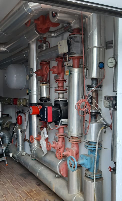
croppedmanifold_zwklli.jpg


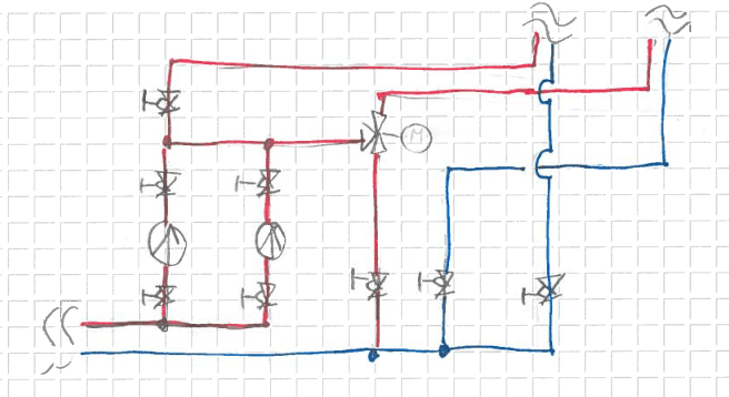
For clarity, this is a P&ID sketch of part of the same manifold:
image_jzxugl.png


I don't understand the position of the three way mixer, as this would mix hot water into the return and serves no function to control the heat of the flow to the HX - it could limit flow to the HX but this does not make much sense energetically (especially considering the cogeneration plant) There's another three way mixer installed near the boiler that could ensure a minimum return temp.
I also miss one-way valves at the pumps.

Context:
This is part of the heating system of a wastewater treatment plant
The large pipes/the right circuit in the P&ID supply the sewage sludge heat exchangers, the small pipe supplies building heating
The heat sources are a sewage gas fired cogeneration plant and a an oil fired boiler, AFAIK the cogenreation plant was added long after the boiler.
Both heat sources have their own feed pump and are connected in paralell, there's a hydraulic compensator
The plant operators could not explain their heating system to me (Lots of automation, sparse documentation)
 
Replies continue below

Recommended for you

Looks like a diverting valve - not a mixing valve. Flow enters the bull of the 3-way and then goes either up or down depending on the valve position, correct? Is the valve 2-position, or does it modulate (I'm guessing 2-position)? I can only assume it is used to prevent the pumps from dead-heading if control valves at the load are closed.
 
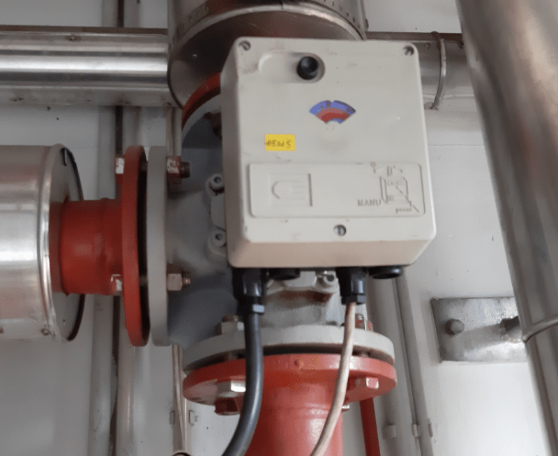
This is a closeup of the valve:

image_stpg5g.png


... appears to modulate and be set roundabout the middle position when I took the picture.
 
So flow is entering from the side and leaving from the top and bottom?
 
Well unless you can find out what is controlling the position of the valve then you probably won't make much headway.

My speculation is that this is either some form of flow control or temperature for the circuit.

Can you draw the rest of the circuit?

Is this a secondary circuit? You say the heaters have their own pumps but not sure how these pumps connect to those pumps or the circuit

The two pumps don't look identical ( one looks smaller). Do they operate one at a time or both at the same time?

I can't see any flow meters in this set up so it is probably temperature control at some location.

Remember - More details = better answers
Also: If you get a response it's polite to respond to it.
 
It appears to be a temperature control. Hot water comes from the left side, cold water comes from the bottom thru your red line (which I think should be blue) and the mixed water leaves thru the upper discharge pipe.
 
For temperature control, the 3-way valve would have to be on the suction side of the pumps.

There are heat meters, the flow meter for the HX circuit is on the return line (uppermost picture, above the blue valve, the flow meter on the return line of the building heating is barely visible to the right of that)

Meanwhile I've found an ancient drawing of the installation. It appears that the return temperature boost near the boiler was added later, so this could be the old return boost.

I'll see when I can expand the P&ID sketch.
 
So to ask my question again, am I correct that the water is entering the valve on the side, and exiting the valve from both the top and bottom ports?
 
So it is diverting part of the flow from supply to return. The question is, why? Where do the pipes on the bottom-left side of your sketch go? They must go back to the heat source. Can you provide more information?
 
Yes the pipes go back to the heat sources. As for the why, that's what I'm trying to find out here, maybe one of you has seen such a system. Or the operators are after all able to provide me the control narrative.
 
Ok, I can't much more than speculate at this point. Two reasons to take perfectly good hot supply water and dump it into the cold return would be:

1. To protect the pumps. If the control valves at the load close, then the pump will dead-head. Opening the diverting valve would remedy this. In that case, it should be operated on pressure or flow.

2. The heat source is a non-condensing boiler and the return temperature is too low. Intentionally bypassing hot water into the cold return will prevent unwanted condensation. In this case, the valve should operate on temperature going back to the boiler.

You need to find out more. At some point, you may want to close the manual valve on this bypass line to see if there are any adverse effects. I would do more investigation first, however, because there may be a good reason for this piping arrangement. You don't want to shut valves without understanding the system, but I have found unnecessary bypass valves open before.

 
It's possibly a recirculation loop back to the boiler. For long pipe runs, there's always standing water in the hot water supply that's no longer hot. In a residential situation, you run the hot water down the drain until hot water shows up at the faucet. But, if you have a thermal switch at the faucet end that connects the hot water to the faucet to the cold water faucet line, you can pump the not-hot water back into the cold water line, which eventually goes back to the water heater. This way, you can "prime" the hot water line without dumping not-hot water into the drain. You could check to see if the valve is controlled in conjunction with the main hot water pump, or an auxiliary pump.

The downside of such a system is that the cold water supply won't be completely cold, so that's a trade-off. The other downside is that the primed hot water isn't necessarily as hot as the steady state hot water, but, you save the water, so there's that.

The alternative to such a system is a completely isolated hot water return line, but that's extra plumbing that might not be feasible or practical to retrofit.

TTFN (ta ta for now)
I can do absolutely anything. I'm an expert! faq731-376 forum1529 Entire Forum list
 
It is diverting, pay attention to how things are piped in relation to the pumps.
 
So here's a more complete sketch:

image_qg6xt6.png


I did not include every valve and sensor. crucially, there's no mixer between the part drawn and the sewage sludge HX.

Everything in a green revision cloud ist not on older drawings, so presumably it was added later. I know for a fact that CHP (combined heat and power plants) where not that common when the heating system was first built.

I've asked for the control scheme but they don't have it (in written form, don't see a way to decompile the PLC programming here)

My assumption is the following:
The mixer served to control the flow to the HX while keeping a constant flow through the boiler, the boiler would operate in on-off mode.
At a later stage, the CHP was added. At the same time the hydraulic ompensator and the return-boost and boiler feedpump was added because the old control scheme didn't make sense with two heat sources.

Presumably the mixer is still used to control flow to the HX since there's no other way to do so (I could maybe test this by analyzing data from the PLC or SCADA, if the valve setting is recorded).

What I still don't understand is why use two pumps without check valves (for redundancy of this critical part).

@BronYrAur
your point 1 is likely part of the reason (would speak for fixed speed pumps, the original installation is from about '84 AFAIK variable speed pumps where not standard in heating systems back then)
point 2 could also be part of the reason, there's a T-sensor on the return line (and apparently was there in the 'ancient' installation)
@IRStuff
It's certainly the recirculation/return (as i've written seomwhere upthread but noone rereads the whole thread every time they post :)), but since the HX is a 24/365 heat consumer I don't think the rest of your reasoning applies.
 
on the basis of that information it looks like it was there to ensure a constant flow through the (single original) boiler regardless of flow through the heat exchangers. This functionality has now been included in the boiler pipework itself, though will a slightly lower mass of water.

So on the face of it you could just isolate that line and see what happens. I suspect very little of note except you might have a little more pressure available to your HX's.

As said before you need to see where the control input is coming from to drive the modualting 3 way valve. If you can't find out then may be one by one take the output from the meters and try and provide different values from that being supplied.

Or little by little screw down the isolating valve next to the blue valve ( looks like a globe type valve to me) and see what happens.

Probably harder for whoever modified the system to remove or change the control logic and they just left it there...


Remember - More details = better answers
Also: If you get a response it's polite to respond to it.
 
@itsmoked, the irony thing is that based on some of the responses, some folks here don't really grasp the fundamentals as to how these systems work. I had a young engineer just like you working for me, plenty of arrogance, wise-guy remarks, and sarcasm..just to hide the insecurities that he was not as smart as he thought he was ;-)
 
Status
Not open for further replies.

Part and Inventory Search

Sponsor