Continue to Site

Eng-Tips is the largest engineering community on the Internet

Intelligent Work Forums for Engineering Professionals

  • Congratulations GregLocock on being selected by the Eng-Tips community for having the most helpful posts in the forums last week. Way to Go!

I have been asked to do this MOD? 2

Status
Not open for further replies.

SteveOOO

Aerospace
Sep 11, 2020
3
I have been asked to do this MOD, I am not 100% certain this is a good idea.
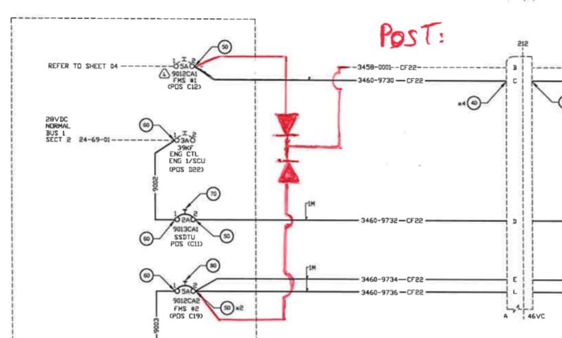
mod_u5nzr7.jpg


Here is my mail registering my concern:

For me it is not possible to do what you have proposed by shunting 2 individual current sources together. As you have 2 different 5 amp current sources which is IT= I1 + I2 (Kirchhoff’s first law states for any junction in an electrical circuit, the sum of currents flowing into that junction is equal to the sum of currents flowing out of that junction) which therefore equals 10 amps and the wires are only 22 AWG not rated to safely carry 10 amps under fault conditions.

Cheers

Steve


Here is the reply i received, and the answer has totally confused me!

Steve,
The failure mode of a diode is shortcut (non rev. blocking) or open circuit. In the case of the Annunciations are powered by BUS1 OR BUS2 thru 2 diodes, there is no effect following diode failures (single or combined) and wire are always protected by CBs.

I know that this kind of design is not common, you are right in this way but there is not technical and no safety issue.

Have a nice week-end

Xavier
 
Replies continue below

Recommended for you

We have to imagine a lot because of the lack of details.

But I agree with you, the modification allows for the full rated current of both breakers to flow in wire 3450-0001. It does not seem that a full failure mode analysis has been performed by the mod's designer.
 
This does eliminate the C/B protection for that output wire.

The only way to understand this is safe is that there is a switch elsewhere that prevents one circuit from being powered at the same time as the other one; that BUS1 cannot have power at the same time as BUS2.

Otherwise if there is a short condition, both BUS1 and BUS2 can supply power to a wire that was designed for BUS1 alone.
 
No there is no switch elsewhere, just directly feeds Annunciations!
 
What is the purpose of running power from both Buses, surely one could replace the diodes with a suitable relay to switch the power supply if the primary bus fails.
 
Hi Steve
This could be a disaster in the making. Stand your ground.
That circuit looks like it would break the reliability principles in FAR 25.1309. Not my sub-discipline of aero engineering but it looks like a barrier diode set, and it's going to be shedding 5-10 Watts constantly, not appropriate for an avionics power supply.

Your colleague is trying to solve a problem that should not exist. I think you need to find out what the REAL problem is that they're trying to solve. Something wrong with the 28VDC Avionics bus? I can speculate - you should investigate.

For everyone's benefit, I'll add what some of the readers can already see in the schematic diagram: the circuits that are being cross-tied are the Flight Management System displays - the primary pilot and co-pilot control interfaces to the navigation system. If you have two of these, you are probably working with an airliner of some kind. Lots of passengers or cargo.

Here's an example (ATR-72 chosen at random). The FMS displays are the pair of displays in the center (beside the co-pilot's left hand) with the keypad.
2339339_trdnv9.jpg


If you have a short to ground (over current fault), conceivably both breakers could trip. When both breakers open, you have lost power for all equipment on both circuits. Is that a tolerable fault?

Also, are they supplied by the same generator and power phase or are they DC power?

My posts reflect my personal views and are not in any way endorsed or approved by any organization I'm professionally affiliated with.
 
Apart from the actual issue, this seems to be a case of two different people looking at two bits of the same mod.

Steve000 is talking about wire 3458 (why is it dashed and the others are solid?), but old Xavier seems to think you're talking about the new red wires leading into the diodes and the potential for back feeding each bus into the other if the diodes fail.

But overall yes it doesn't look like a good move to me.

Remember - More details = better answers
Also: If you get a response it's polite to respond to it.
 
Status
Not open for further replies.

Part and Inventory Search

Sponsor