Hi everyone,
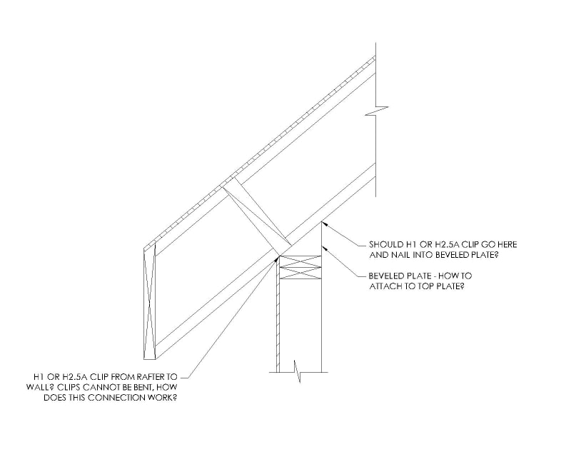
I'm currently drawing some generic details for future use. One of the details I need is where an I-joist is used as a rafter and connects to the wall framing. Where I am contractors almost exclusively use I-joists for roof rafters instead of dimensional lumber. I have seen details that other engineers use, including my old firm, and they all specify that either a Simpson VPA connector or a beveled plate is to be used for the rafter to bear on. If a VPA connector is used then my question is moot. But, if a beveled plate is used then there are a few issues that I can't answer to my satisfaction. I have yet to see one of these details where the connection from the beveled plate to the top plates is specified. If the rafters are at a steep pitch, say 10:12 or more, then that beveled plate will be quite thick and I don't see how to connect it to the top plates without some very long screws.
Second question is that on these typical details I've seen, a Simpson H1 or H2.5A clip is specified for the rafter to attach to the top plates at the outside of the wall. See the drawing below. The H1 and H2.5A clips cannot be bent so I don't think they will work in this application. Should they be placed on the inside of the wall and nailed into the beveled plate? You think that's ok? I would feel ok with that if I could come up with an adequate solution for attaching the beveled plate to the top plates.
To summarize...
1) How to attach the beveled plate to the top plates? Super long screws? LTP angles? A35 clip?
2) How to attach the rafter to the beveled plate/top plates? H1 or H2.5A on the inside and nail into the beveled plate?
Thanks!