Effective moment of inertia (the value you might actually use in an analysis for assessment of deflections) simply scales/adds in another component on top of the I_cracked value to address tension stiffening effects. This accounts for the bits between the cracks stiffening things up as they are not fully cracked through to the neutral axis depth.
In a cracked section the neutral axis is at the depth of zero strain obviously, this is true at the ultimate and serviceability limit states (plane sections remain plane and all that good stuff). Once there is an axial load I believe however that the following statement is not true:-
cracked neutral axis calculated with sum of moments of the transformed areas about the neutral axis = 0.
This is is true for pure bending. For bending there is internal equilibrium (so the 1st moment of area approach works), with an external axial load this load needs to be factored into the analysis somehow.
I'd assumed from the original question that it was some sort of building core carrying
flexure and
axial loads, so axial would need to be considered (though Kootk can weigh in on that).
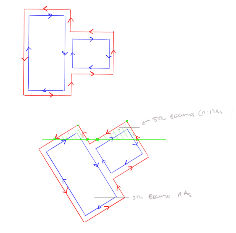
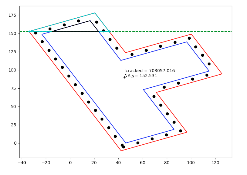
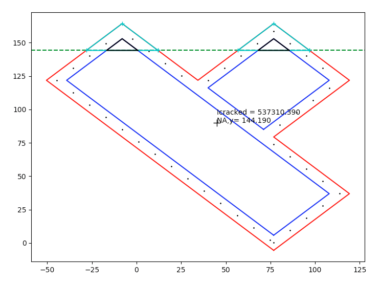
Therefore an alternative approach is to recognise that the reinforcement and concrete stress is linearly related to the distance from the neutral axis. Then work using force or moment equilibrium to solve for the NA depth including the axial load. For a simple beam and a triangular stress block this means the centroid of the concrete force is simply 1/3 x NA depth down from the extreme compression fibre. However for highly irregular sections like your test sections its not so simple obviously assuming you have an axial load and irregular geometry!
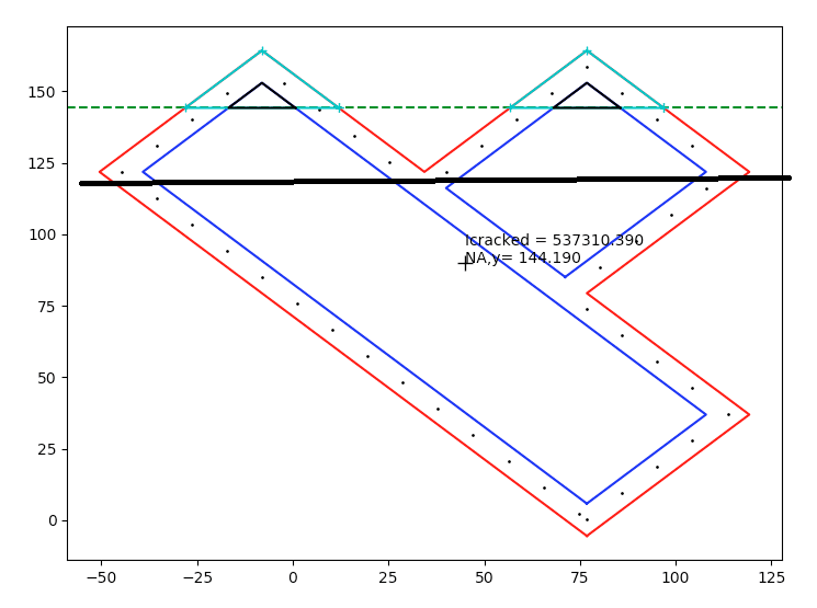
But if you already have it sliced into polygons and you know the strain because you know the depth, you can work out the stresses and hence integrate numerically the 'volume' of stress over the depth of the slice and width (assuming in most cases its broken down into a shape with linear edges) to find the total force and the centroid of this force in each layer (even using something as simple a simpsons rule can work here).
In VBA at least this was starting to get real messy as I was actually doing it at the ULS and looking at using the Eurocode parabolic compression block, so the stress varied parabolically over the depth of a given slice. I had all the numberical integrate bit working using the Tanh-Sinh quadrature routine posted on IDS's website, but it was the slicing bit I was having issues with under a few cases as I never thought of having +ve concrete -ve void approach like you are doing (I was doing something completely different that in hindsight looks like I was way off on a tangent), so I put it on hold a while back and never came back to it!
FYI, an excerpt from my old university notes (attached if its any help) say to either find the neutral axis position by
[ol 1]
[li]1st moment of areas (which is ok if there is no axial load) or (Your approach, and my notes state this verbatim)[/li]
[li]trial and error in balancing forces[/li]
[/ol]
I've always gone down the trial and error balancing forces approach myself and completely read over the 'for force equilibrium the sum of transformed area about the neutral axis = 0' alternative which is why I questioned things!
EDIT - Celt83 I see your edit regarding plastic neutral axis as I was typing this up, I am referring to the neutral axis at serviceability. The term plastic neutral axis and Icr at ULS doesnt have much meaning to me, maybe its in codes other than mine and has some practical design use.
I think at serviceability, you are correctly working it out if there was no axial load.

") .
.