Eng-Tips is the largest engineering community on the Internet

Intelligent Work Forums for Engineering Professionals

  • Congratulations waross on being selected by the Eng-Tips community for having the most helpful posts in the forums last week. Way to Go!

I need a help regarding flange factors........

Status
Not open for further replies.

gotothesky

Mechanical
May 14, 2019
57
KR
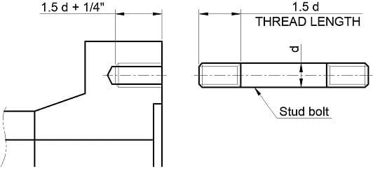
I would like to design Studding flanges for high pressure exchanger.
Commercial software for pressure vessel calculation dose not provide Design option of Studding flange.


studding_flange_rdzwpr.jpg


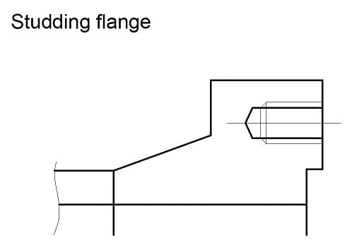
Due to above reason, I have to make strength calculation sheet for flanges.

But, I am very sorry that I have a big problem during making calculation sheet.

In ASME Sec.VIII APP.2 Table 2-7.1, flange factors' Formulas are extremely complex!!
I checked Formulas so many times. But, I can't find out any error.
But results of F / V / f are minus values.

Is there any guy who can teach me what is wrong?
I attached excel sheet that I am making for flange calculation.

Regards,

 
Replies continue below

Recommended for you

gotothesky, I am assuming Sec VIII, Div 1 here:

Calculations in your spreadsheet of the various factors A thru E6 are complex and tedious. I do not propose to check them for you.

I can say that, referring to Figs 2-7.2, 2-7.3 & 2-7.6 that F, V, F are approximately equal to:

F ~= 0.75
v ~= 0.12
F ~= 1.15


I conclude you have errors in calculation of the factors A thru E6.

Do you have access to any software you can cross-check your spreadsheet with? Might be your best hope...

EDIT: On further reflection I am not familiar with software that provides that level of detail

Regards,

Mike

The problem with sloppy work is that the supply FAR EXCEEDS the demand
 
I had the same problem years ago. I decided to use the figures and not waste any more time.

Regards
 
Yes, it's fast and, if a little careful, you don't give up a meaningful degree of accuracy.

The problem with sloppy work is that the supply FAR EXCEEDS the demand
 
r6155

I am considering your proposal also.
It's so time-consumable and I am so tired!
 
Be careful, this design is to hold the stud in position during disassembly. The stud must not rotate, the flange threads may be damaged. Once installed, avoid removing the bolts.

Regards
 
r6155

Thank you for your expert confirmation!
How can I fix stud bolts to Flange?
Can I do tack weld between stud bolts and flange?
The other side of stud bolts will be assembled with heavy nuts.
I think my idea is slightly ridiculous.
But, Tack welding may be broken easily due to bolting load!

Is there any good idea to fix stud bolts to flange?

Regards,
 
The Appendix 2 formulas are complex, but I do have a spreadsheet for them.

I do not open .xls or .xlm files from the Internet. However if you post a .xlsx file I could compare your results with mine and see where they differ.

Geoff
 
gotothesky
1) Never do any welding on the bolt.

2) See more reading in ASME PCC-2 Article 303
The design requirements of equipment such as vessels,
machinery, valves, instruments, etc., where close coupling
is required because of operational, economic, or space
considerations, often dictate the use of tapped holes;
usually with a stud, but sometimes with a cap screw.
When a stud is used, the stud is engaged within a
drilled and tapped hole at one end and secured with a
nut at the other end. The threads in the tapped hole
often have a tighter fit with the stud than do the
threads in the nut. The tighter fit usually is specified,
and the stud is usually bottomed in the tapped hole, to
facilitate removing the nut from the stud without
removing the stud from the tapped hole. Threads in
tapped holes often are damaged when studs are
removed after a period of service


A standard taper tap will produce incomplete tapped
threads near the bottom of the tapped hole; even the
use of a bottoming tap will not ensure a complete final
thread. As a consequence, bottoming a fully threaded
stud into a tapped hole that has incomplete threads
near the bottom damages the full threads on the end
of the stud. This almost ensures that the full threads in
the tapped hole will be damaged as the stud with
damaged threads is backed out. A practice that has
been used successfully to prevent this from occurring
is to remove some of the threads from the studs and
to increase the depth of the tapped holes accordingly.
A sketch with suggested dimensions is provided in

Regards
 
r6155

In Pressure vessel design manual 4th ed. by Moss,
A length of Tapped holes on flange is specified as( 1.5 x Dia. of stud + 1/4" ).

the above length seems too long!
When assembling Stud bolts to flange's tapped holes, Stud bolts are always tightened seriously??
I think Stud bolts insert into tapped holes by 1.5 dia. of studs and the other depth, 1/4" is considered as margin!


gotothesky, UG-43(g) gives rules for depth of tapped holes. You can likely go less than 1.5*d.

Studs are sometimes made with extra length (say 1*d) and wrench flats formed on the extra length. This provides a means for removing the studs without double-nutting or using special tools. The studs also may be held when breaking the nuts.

The problem with sloppy work is that the supply FAR EXCEEDS the demand
 
gotothesky

This design requires a experienced fabricator, careful machining, extra clean of tapped hole, etc.

Why did you choose that design for a heat exchanger?, What is the design pressure?

Regards
 
r6155

Exchanger's design pressure is so high(about 150 barg)!
We can reduce B.C.D(Bolt Circle Diameter) with Studding flange.
It means we can reduce flange moment, and reduce size of flange!

STUDDING_FLANGE_gymw2d.jpg


I plan to studding flange as above!
How about it!

regards,
 
gotothesky, see UG-12(b) for design of stud bolts themselves,

A remark: For such pressures alternatives to bolted joints are often used, except perhaps for small diameter units. See TEMA Type D channels.

EDIT: 500 mm could probably be considered "small diameter".

The problem with sloppy work is that the supply FAR EXCEEDS the demand
 
API 660 9th edit 2015

7.7 Flanged External Girth Joints
7.7.1 Channel and shell external girth joints shall be of through-bolted construction. Studded-in bolts may be used
when specified or approved by the Purchaser

See: API 660 9th edit Addendum 1(2020)
Internacional Association of Oil & Gas Producer
SPECIFICATION S-614 DECEMBER 2018

Supplementary Specification
to API Standard 660
Shell-and-Tube Heat Exchangers

7.7 Flanged External Girth Joints
7.7.1
Replace second sentence with
Studded-in bolting shall not be used.

Regards
 
r6155

I noted your comments!
But, Some clients want smaller size of body flanges!
I really want to perform All Pressure part calculations with only commercial software.

But, If that is a client request, I will do it!
Before application of Studding flanges, I try to mention general codes' and standards' requirements as per your comments!

Thank you so much for your expert comments!

Regards,
 
gotothesky, from the standpoint of Apx 2 design I would not consider your studding flange any different than a thru-bolted design. Note that: a) There are no restrictions on the "R" dimension, b) there are no variables or calculations accounting for the presence of the bolt holes, that is they are disregarded.

I suppose it is possible your software will not permit or override some dimensional inputs or will generate error messages.

The problem with sloppy work is that the supply FAR EXCEEDS the demand
 
SnTMan

I have already completed Flange calculation using excel sheet!
I confirmed calculation result with commercial software's result.
Reacting forces and others are almost same! but, But, Factors and Hub correction factors are different.
Due to difference of flange factors, my calculation result shows thicker thickness of flange than that of commercial!
I will carefully reconfirm flange factors later!

Sometimes, clients insist strongly their request! In that case, I have to follow!

Regards,

 
As noted above, I can compare my Excel results for equations (1) thru (45) in Table 2-7.1 to yours to see where they differ if you post an .xlsx file.
 
gotothesky
"Sometimes, clients insist strongly their request! In that case, I have to follow!"

Ummmmmm !

It is your responsibility to make complete calculations. ALWAYS !!. The client pays for that !

Regards
 
Status
Not open for further replies.

Part and Inventory Search

Sponsor

Back
Top