Continue to Site

Eng-Tips is the largest engineering community on the Internet

Intelligent Work Forums for Engineering Professionals

  • Congratulations MintJulep on being selected by the Eng-Tips community for having the most helpful posts in the forums last week. Way to Go!

Ideal CT location for differential protection 1

Status
Not open for further replies.

sparkview

Electrical
Nov 12, 2015
59
Dear all,

Consider the configuration below. The protection scheme consists of a RET615 protection relay with included overcurrent and differential protection for the Transformer. The CT's on the secondary side of the Transformer is still pending to be installed, however, there is not much space to install CT's at the switchgear in Substation 2 (location 2). Would there be an issue installing the CT's at 'location 1' near the Transformer secondary side? Also, any pointers with regards to IEEE, NEC reference is greatly appreciated.

FESS_CT_location_ourlcq.jpg
 
Replies continue below

Recommended for you

It would be even better if you could overlap the breakers to be inside of the transformer differential zone. This would cut down on any arc flash hazard at that breaker location. However, it is probably unlikely that there is enough room for protection CTs on the bottom side of that 480v breaker.

Google overlapping zones of protection

GarrettFig1-ZonesProtection_bp3k9n.jpg
 
CTs on the line side of the breakers would be an improvement, if feasible. Locating the 480 V CT between the breaker and the bus is probably going to be difficult in the real world. The more encompassing the differential zone is, the better the protection. Should be completely feasible on the primary side.
 
Hi all,

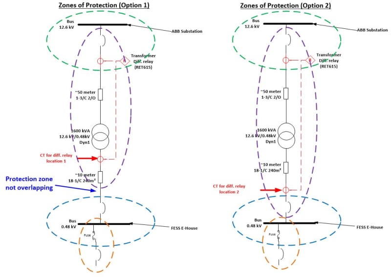
Thanks for the prompt replay. So if I can interpret the overlapping protection part correctly as shown below, Option 1 is not an overlapping protection configuration compared to Option 2?

FESS_CT_location_not_overlapping_hun6xd.jpg
 
zone boundary is defined at the CT location if it is protected by a breaker. If it is protected by fuse, the fuse location is the zone boundary. You might need to slightly adjust the circled region to stop at the CT.
 
Hi all,

So, in this case, the following image should represent the current situation, the most right diagram been the one ideal?

FESS_CT_ydhdmq.jpg
 
Yes, for the purple 87T zone of protection. I can't speak for the green, blue, or yellow zones since I don't know where their CTs are located or what type of relaying is used.
Option 1 appears to be inaccurate if the blue zone is the fuse, it is different than the other two.
 
The yellow zone seems to pick up a portion of the bus and ends at the fuse, probably incorrect.

Where is/are your sources?
 
Status
Not open for further replies.

Part and Inventory Search

Sponsor