Continue to Site

Eng-Tips is the largest engineering community on the Internet

Intelligent Work Forums for Engineering Professionals

  • Congratulations MintJulep on being selected by the Eng-Tips community for having the most helpful posts in the forums last week. Way to Go!

Ideas requested on how do to fix this backfeed issue on a parallelled 480V system

Status
Not open for further replies.

bdn2004

Electrical
Jan 27, 2007
794
There are two identical 480V switchgears located 1000' apart. Both are fed through 12.47kV-480V, 1500kVA transformers. Both switchgears have a secondary main breaker and secondary feeder breakers. All the protection on the breakers are set up the same of the same size.

Here is the issue: Should a fault occur where shown on BUSWAY 1A the East Breaker will open - but because of all the resistance of the busway back to the West - it doesn't open it's paralleled breaker at the same time.

FDR BKR 2 WEST however does open, and so does the main on that side, cause they are faster.

What is desired to happen is that on a fault on the particular bus is that both breakers feeding it open - and none of the others.
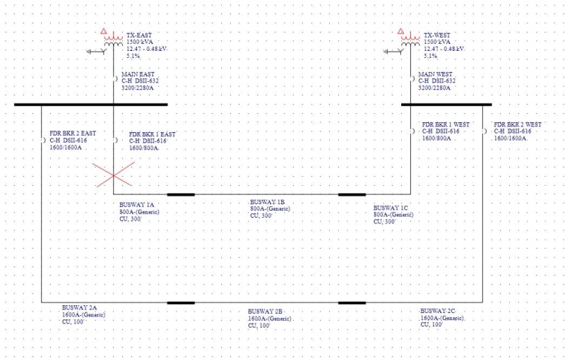

Parallel_480V_bus_duct_feeds_qmhbks.jpg
 
Replies continue below

Recommended for you

First off, you shouldn’t have an 800A bus running in parallel with a 1600A bus. That said, it shouldn’t be terribly difficult to coordinate the settings if there’s as much impedance as you suggest. Line current differential is made for applications like that. A POTT scheme could also solve the problem.
 
There are different size bus ducts connected - what's the issue there?

I've exaggerated the numbers to try to show the issue. But in general the dual fed busducts are hundreds of feet long. This is a real situation I've found doing one of these studies, however this isn't the actual data. Sometimes the wrong breakers trip depending upon where the fault is.

Thanks for the advice on line current differential and POTT scheme.


I believe that for a fault on the busway 1, the breakers 1 should be able to isolate the fault (tripping Bkrs 1E & 1W).

If subsequent, the breaker 1W fail to open, both breakers on the West bus (Bkr W2 & the Main Bkr W) should be able to isolate the fault predicated on busway 1.

It is recommended that the protective device coordination and settings should be reviewed closely
 
OP you have a RING BUS configuration, so go google ring bus protection schemes.

For protection coordination to work properly you need to have two CTs summed up (in parallel) and that breakers trip in pairs. 1E and 1W are paired, CTs from 1E and 1W are summed in the same relay that would control both 1E and 1W. In your fault example, the two CTs on 1E and 1W would both see same direction of fault current and when summed together, the relay trips both 1E and 1W. During this fault, 2E and 2W also see fault, but since the current flow on one side is in the opposite direction, the summed CT output cancel therefore no trip.

In the event that 1E or 1W fail to trip (breaker fail) then you can use Main E or Main W as back up. this can be easily coordinated by having a slower speed than the downstream breakers.
 
protoslash,

"1E and 1W are paired, CTs from 1E and 1W are summed in the same relay" ... These two subs are 1000' apart. Is there a way to do this without running the CT wiring between the two? Two relays and a fiber signal between the two or something ?
 
That’s not a ring bus. It’s two simple buses with paralleled ties.
 
my bad, didn't see the bus is 1000ft apart. However the concept is the same, electrically it is a ring with long ties. The scheme I described still works, 500ft of CT wire is doable you just need thicker wire and higher burden CT rating.

where is the load connected? if not on buswayA/B/C, line differential could work but you run into the same problem of long CT wires.
 
The loads are fed through fusible bus plugs that are connected to these 10' long busway sections. Some busses could have 100 sections or more. Most loads are close to the busways, but some aren't. This is a manufacturing plant that changes it's processes often. Some of the loads are MCC's, power panels, and welding machines.

I've not the time right now to dig into this. It's just something I ran into when running the software: strange results on what trips during a fault at particular sections of the busway.

I'll first try just changing coordination, but I'm thinking that's gonna take some work to make sure both breakers are tripping, and none of the others. And do it for every section and on multiple busses.
That's why I like what you are saying. Let's get a solution that will work no matter what that I can propose to our Client.


No, it's not a ring bus and the 1000ft doesn't have anything to do with it. The breaker arrangement just isn't that of a ring bus.

Line differential works over fiber, not copper, and can be set to not operate on load. A POTT scheme, also set to only operate above load, could be done with some fairly simple directional overcurrent relays and some simple comms. An SEL-751 at each end would work; I'm sure there's lots of other options as well. The breakers' built in trip units won't do the job.
 
You are saying the regular trip units won't do the job? That was my original thought...why not just shunt trip the other breaker on the opposite side with some auxiliary contacts from the breaker that does trip. Too slow?

The software is showing it is the reverse current through the wrong breakers, that are feeding the fault. There's like 10kA of fault current that get sensed.

BTW the Utility just put in a ring bus on the system that feeds this on the primary side of the transformer.
 
Status
Not open for further replies.

Part and Inventory Search

Sponsor