Continue to Site

Eng-Tips is the largest engineering community on the Internet

Intelligent Work Forums for Engineering Professionals

  • Congratulations KootK on being selected by the Eng-Tips community for having the most helpful posts in the forums last week. Way to Go!

Identify the lateral load resisting system 2

Status
Not open for further replies.

Blackstar123

Civil/Environmental
May 5, 2013
253
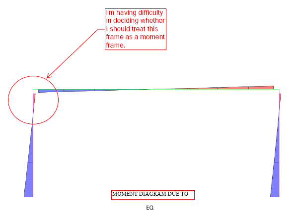
I'm having difficulty in identifying the type of lateral resisting system for the following frame.
Should I called this a moment frame or a Cantilever Column?
image_uornwa.png


If I look at the moment diagram for combine load cases, I'll identify the following first two cases as moment frame. But again for the third case, I can't say that the frame is a pure moment frame with any conviction.
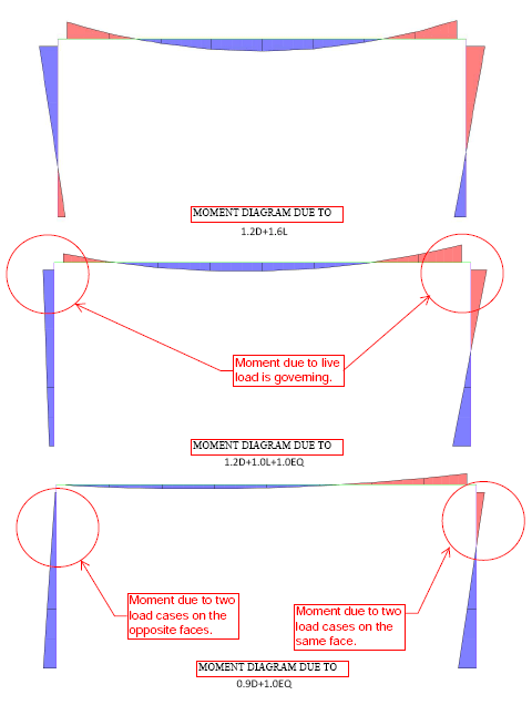
image_g26dmo.png


I would like to learn how would other engineers will deal with a situation like this.

Thanks in advance for your help.

If anyone want to know the backstory behind this question, they can find it at this Link
 
Replies continue below

Recommended for you

Ask the person who made the model. Without a design intent, it can’t be modeled. However, it looks like it could be a fixed base moment frame.
 
That is a moment frame. There is fixity between the columns and the beam.

I can't tell you what type of moment frame. To be safe, you could assume R = 3.

DaveAtkins
 
Looks like a fixed base moment frame with a beam much weaker than the column. When the beam is loaded (1.2D+1.6L), all of the moment has to be resisted at the beam ends and transferred to the columns. A lateral load, on the other hand, is going to be resisted by the stiffest points of the frame. If the beam is much less stiff than the column, the fixed column base will "attract" more (or, in this case, nearly all) of the load.
 
DaveAtkin and PhamENG, thank you for responding.
The goal here is to identify the collapse mechanism and justify using a particular R value. I hope you can help me figure this out.

WannabeSE,
Actually, I'm the one who's designing this frame. I want it to act like a moment frame for lateral as well as gravity loads.
However, I can see that the frame has a mind of its own when it comes to EQ load case.
Two things are happening here.
1. Beam joints aren't stiff enough.
2. Live load is relatively high.

For the sake of argument, let's assume I can't increase the beam stiffness or reduce the beam span.

I know the idea behind designing for inelastic EQ forces is to provide necessary ductility to ensure that the structure would go large inelastic deformation before collapse.

But,
1. When we say the lateral load resisting system is a moment frame, do we look at the combine load behaviour or EQ alone?
2. If I detail it as an IMRF moment frame, would it provide the required ductility for lateral load for this particular case?

I think if I look at combine load case, I may be able to justify using R for IMRF, but I'm looking for a very convencing explanation.

I seem to be missing some key understanding here and I can't put my finger on what that is. Do you think plastic analysis will help reaching to a definite conclusion.
 
I don't understand the issue here. It's either a moment frame or it isn't. If you say it's an IMF it needs to meet the requirements of AISC 341. If you use an R=3 you can avoid AISC 341. Still have drift limitations per ASCE7 you need to consider.

 
To what standard are you designing? Are you going for prescriptive requirements (IBC, AISC, etc.) or are you going for a Performance Based Design? If the former, then you don't need to worry as much about how it performs outside of drift limits (and, of course, serviceability checks) - just detail it according to AISC 341 as Rabbit12 said. If you're doing a PBD, then you'll need to review whatever standard has been adopted by your AHJ (there are a couple of them out there). I'm afraid I can't help much here - my interest with PBD is still in the fledgling stage and I can't offer any practical advice.
 
Do you think plastic analysis will help reaching to a definite conclusion.

If you mean a pushover analysis, this is the best way to demonstrate the exact failure mechanisms in play here.

But you can probably do it incrementally by hand knowing what the various capacities of the members are. Just redistribute the load until a mechanism is formed. For a fixed base moment frame this is going to be a hinge each end of the beam and hinges at the base of the columns assuming the columns are stronger than the beam.
 
It is a moment frame. It is just a co-instance that, in case 3 left joint, the negative moment was balanced out (visually) by the lateral load induced positive moment. That does not indicate the column behaved as a cantilever, otherwise, the moment at the column lower end should be larger.
 
I've come with some sort of explanation for the questions I asked.

me said:
1. When we say the lateral load resisting system is a moment frame, do we look at the combine load behaviour or EQ alone?

As most of the people have already pointed this out, but I'll quote rabbit12 which I find most concise.
It's either a moment frame or it isn't.
The percentage distribution of end moments in the columns for the lateral load case was the major source of confusion for me.
But I've come to realize that, the behaviour due to lateral load may looks like a cantilever action, but one major difference between an actual cantilever and frame acting like a cantilever is that, an actual cantilever will become unstable in case of plastic hinge formation at the fixed support, whereas a frame will distribute the load if it has the appropriate joint capacity.

Thus, if properly detailed, the distribution of end moments will not matter.

Which brings me to my question no. 2

me said:
2.If I detail it as an IMRF moment frame, would it provide the required ductility for lateral load for this particular case?

For my case, maximum moment due to EQ are near the support which will start to yeild first, once Mp is reached. And conceptually, this is the location which should be ductile enough to prevent the total collapse of the frame.

So to answer the question, I think so it will. But it'll not hurt to look at the detailing requirement for a cantilever column and incorporate it in my design too.

The major problem I had with a cantilever lateral force resisting system was its very low R value, which I now can justify why doesn't apply for a moment frame.

The only problem that remains is that the plastic hinges will be formed at supports first, which I know, is not the desired mechanism for a lateral force resisting system, because it will result in very high P delta forces.

So my first plan of action here is to somehow increase the joint stiffness to shift the end moments towards the beam column joint. I'm thinking of using haunches. A member of this forum has also recommended diaphragm plates in the beam-column connection.

I'll appreciate if someone could recommend other feasible and effective solutions.

There's a clear height limit in this frame. Therfore, increasing the beam depth is not possible here.
 
rabbit12 said:
If you say it's an IMF it needs to meet the requirements of AISC 341. If you use an R=3 you can avoid AISC 341.

PhamENG said:
To what standard are you designing? Are you going for prescriptive requirements (IBC, AISC, etc.) or are you going for a Performance Based Design?

Yes, I'm designing as per AISC341 provisions.
I've studied the performance based design theory in my MS, but I have already forgotten it because of lack of practice. My to study list is getting bigger and bigger everyday.

Agent66 said:
If you mean a pushover analysis, this is the best way to demonstrate the exact failure mechanisms in play here.

I was thinking of hand calculation.
But, I think it will be advisable to perform a push over analysis taking into account the P delta effect.
 
1) I'm not sure if everyone commenting here realizes it but, as stated in the related thread, the columns here will be 36" x 36" concrete filled HSS. Serious stuff.

2) For any situation requiring meaningful seismic ductility, I vote for calling this a cantilevered column system rather than a moment frame. Consider why we punish cantilevered column systems which concentrate energy dissipation in the column base connections:

a) This concentration means limited redundancy.

b) Base connections are difficult connections at which to dissipate energy reliably. At such locations, you've got to deal with flexibility originating with the anchor bolts, the base plates, the footings, and the soil.

I feel that, based on the relative proportions of the frame beams and columns here, both of the above apply to OP's system and, therefore, it warrants treatment as a cantilevered column system. With the current proportions, and the need to form column base hinges either way for mechanism formation, there just isn't any way to trick this thing into denying its true nature and somehow dissipating substantial energy through the beam hinges.

3) For P-Delta under the gravity load combinations that would plastify the beam-to-column joints, keep in mind that your leeward joint will effectively be pin. And means that you'll be stuck using mostly the windward frame alone for stability. This is, of course, another compelling argument to use a cantilevered column system for this. Although, based on stiffness, your frame will wind up being a cantilevered column system of its own volition for this purpose.

4) This last point will be a bit frou-frou as I'm as yet unable to fully identify and articulate my concerns on this. I am fundamentally discomfited by ductile lateral system that might form plastic hinges at the joints under gravity loading. That, even if the gravity plastification would only occur under the gravity only load combinations. Things that nag at me:

a) Lateral ratcheting, and it's affect on P-Delta, if the frame will be plastifying cyclically.

b) When the hinges plastify and then load is removed, there will be some stresses locked into the section. Does this affect the joint's ability to dissipate energy in a predictable way? Perhaps not given that:

i) I believe that, in subsequent excursions into inelasticity, one can "push" through any locked in stresses to reach the same plastic stress distribution assumed of a fresh beam.

ii) Earthquake loading assumes that there will be repeated, reversing inelastic excursions of the frame plastic hinges.
 
Kootk, Thank you so much for putting a lot of thought into my problem.

I've been playing around with different beam/column sizes today, and short of reducing the span length, there's no practical way to equally distribute the end moment between support and the top joint. The only compensating advantage of increasing the beam size, is that requirement for end releases will become avoidable for gravity load case. Still since the ultimate moment is somewhere between the elastic and plastic capacity, your concerns in point No. 4 seems valid.

But, isn't the practice of designing a beam to achieve plastic capacity for an ultimate gravity load combination quite regular? Then why does code not voice any objection on such a practice for structures in moderate or critical seismic zones?

Also won't concern for lack of redundancy become redundant if I provide a sufficient beam capacity to be able to resist the moment redistribution?

If above is true, than in my opinon the issues which should be dealt with great care are
1. your point no. 2 that is,
Kootk said:
Base connections are difficult connections at which to dissipate energy reliably. At such locations, you've got to deal with flexibility originating with the anchor bolts, the base plates, the footings, and the soil.

2. P delta effects
3. Story drifts


I've been searching the web for some sort of approved base plate connections for cyclic loading for a situation similar to mine, but couldn't find any.

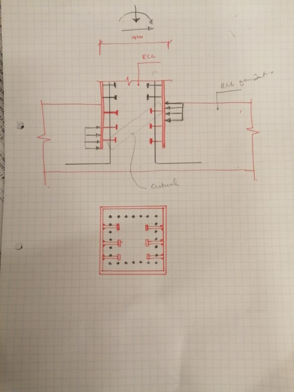
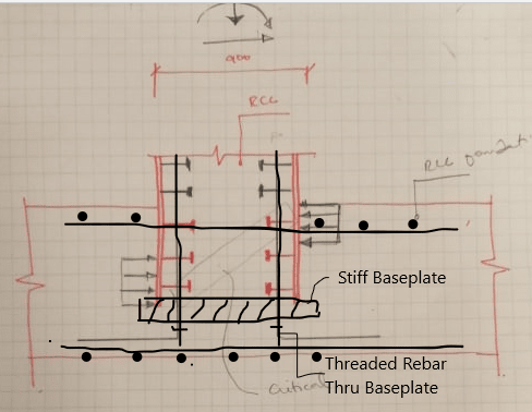
I'm thinking of providing a base connection like shown in the picture, which I think would be more ductile than the anchor bolts assembly.
What I've observed in the short time in this forum, is that connection detailing is considered your forte. I'd greatly appreciate your thoughts in this regard too.
Edit: Some relevant information
Gravity load combo, e = M/P = 0.3m
1.2D+L+EQ, e=0.7m
2.0.9D+Eq, e=2m
EQ loads with R for IMRF

IMG_20200227_180122_yqglsa.jpg
 
I feel like you'd need some internal stiffeners to get that bearing mechanism to work.

That type of action you're proposing is similar to how steel coupling beams embedded into concrete walls work. Though usually you need significant embedment length to make it work.

Another option could also be to have a horizontal steel member in the footing to provide the fixity.
 
Agent666, first of all, thank you for your thoughts in this matter.

I've some questions and some ideas to bounce off you, regarding your reponse above.

I feel like you'd need some internal stiffeners to get that bearing mechanism to work.
Are you talking about the bearing due to the shear force, or due to the axial force?
I don't get why column needs to be stiffened if it's filled with concrete.

That type of action you're proposing is similar to how steel coupling beams embedded into concrete walls work. Though usually you need significant embedment length to make it work.
A 1200 mm footing depth is required for EQ loads with an R for IMRF. I've never designed a connection for column embedded in foundation, so I don't have an idea how long an embedded depth will be required here, but I'm hoping it'll be less than the provided footing depth. I'm running ragged to make one element of the structure to be safe, only for others to start failing in some other limit states. [morning]

About the coupling beam type of behaviour, Yes, I saw a diagram of beam embedded in RCC in the code, when I was going through it looking for provsions for base plate design. I'll have to study it in detail to find out how it can relate to my situation.

Another option could also be to have a horizontal steel member in the footing to provide the fixity.
Won't it further complicate an already complex stress situation in RCC foundation?
Shear studs welded inside the tube will be serving to stop the slippage between RCC and steel tube and rebars will provide the development length required for bending moment. There is no uplift in the columns. Even for load combination = 0.9D+EQ.

If fixity condition is not met with rebars and shear studs than won't you think the next best option will be the anchor bolt assembly embedded in foundation? I'll just have to make sure that anchor bolt doesn't yeild before the steel columns.
 
How about detail like this?

Ftn_ie1nue.png
 
Retired13,
The detail you're proposing would be advisable if I weren't providing a monolithic connection between column and foundation. The detail I've proposed, I don't see bearing due to vertical load be a problem in the sense you're implying. In my opinion, the development required for tension force and bearing due to shear force will create problems here. However, I'm aware that the bearing of the whole column on RCC foundation will need to be checked.
 
blackstar123,

Actually our details are quite similar in the manner how they work. I think my detail allow the elimination on the internal studs. Note that the in either case, there will have tension at the HSS-concrete interface that need to be addressed.
 
Blackstar123 said:
Kootk, Thank you so much for putting a lot of thought into my problem.

You're very welcome, it's bee interesting to follow.

Blackstar123 said:
..there's no practical way to equally distribute the end moment between support and the top joint.

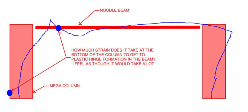
Unless base flexibility is accounted for, there really is no way to equally distribute the moments. And that leaves us with the interesting question of just how much moment parity is required? I don't know the answer to that other than to apply my own judgment under the expectation that there is some reasonable limit that should apply. See the clip below for a hyperbolic example.

Blackstar123 said:
But, isn't the practice of designing a beam to achieve plastic capacity for an ultimate gravity load combination quite regular?

Doing it for a beam that is not part of the lateral system is quite common. I don't believe that I've ever seen it done for a lateral, moment frame beam.

Blackstar123 said:
Then why does code not voice any objection on such a practice for structures in moderate or critical seismic zones?

Perhaps because it's of little consequence for the usual case of a gravity only beam that is not designed to be part of the lateral system. It's important to recognize, however, that the codes and standards that we use are not intended to be all encompassing. An engineer's own judgment must reign supreme.

Blackstar123 said:
Also won't concern for lack of redundancy become redundant if I provide a sufficient beam capacity to be able to resist the moment redistribution?

Perhaps, if you can reconcile yourself with the strain compatibility issue that I've presented below. It must be kept in mind, however, that the frame will continue to draw seismic force until the bases form plastic hinges. The force level associated with that action may well negate any R-value benefit from calling the thing a moment frame.

c01_hp64as.jpg
 
Status
Not open for further replies.

Part and Inventory Search

Sponsor